
ABNORMALITY DIAGNOSIS APPARATUS AND ABNORMALITY DIAGNOSIS METHOD FOR NOx SENSOR

a technology of nox sensor and abnormal diagnosis apparatus, which is applied in the direction of electrical control, instruments, machines/engines, etc., can solve the problems of inability to provide an on-board diagnosis, inability to find effective techniques, and high cost of cases

Inactive Publication Date: 2011-01-06
TOYOTA JIDOSHA KK
View PDF7 Cites 26 Cited by
  • Summary
  • Abstract
  • Description
  • Claims
  • Application Information

AI Technical Summary

Benefits of technology

The present invention provides an abnormality diagnosis apparatus for a NOx sensor in an internal-combustion engine. The apparatus includes a selective reduction NOx catalyst, an after-catalyst NOx sensor, a reducing agent addition means, before-catalyst NOx concentration acquisition means, abnormality determination means, and an idling control means. The apparatus can accurately diagnose abnormalities of the after-catalyst NOx sensor by comparing the detected NOx concentration with the before-catalyst NOx concentration and the estimated NOx concentration value based on operating conditions of the engine. The apparatus can also stop the engine and diagnose the after-catalyst NOx sensor during idling. The reducing agent addition means stops adding reducing agent when the NOx catalyst is not within a predetermined temperature range. The method can be carried out using urea as the reducing agent.

Problems solved by technology

However, as described above, regarding the detection of an abnormality of a NOx sensor provided at the downstream side of NOx catalyst, no effective technique is found in the current situation.
However, the former case requires a high cost and the latter case fails to provide an on-board diagnosis.
Specifically, the output value from the NOx sensor undesirably reflects an influence by the NOx absorbent in front of the sensor, which causes a deteriorated accuracy of the abnormality diagnosis of the NOx sensor.
This is a technique regarding a storage-type NOx catalyst and cannot be directly applied to a selective reduction NOx catalyst.

Method used


Image

  • ABNORMALITY DIAGNOSIS APPARATUS AND ABNORMALITY DIAGNOSIS METHOD FOR NOx SENSOR
  • ABNORMALITY DIAGNOSIS APPARATUS AND ABNORMALITY DIAGNOSIS METHOD FOR NOx SENSOR
  • ABNORMALITY DIAGNOSIS APPARATUS AND ABNORMALITY DIAGNOSIS METHOD FOR NOx SENSOR

Examples


first embodiment

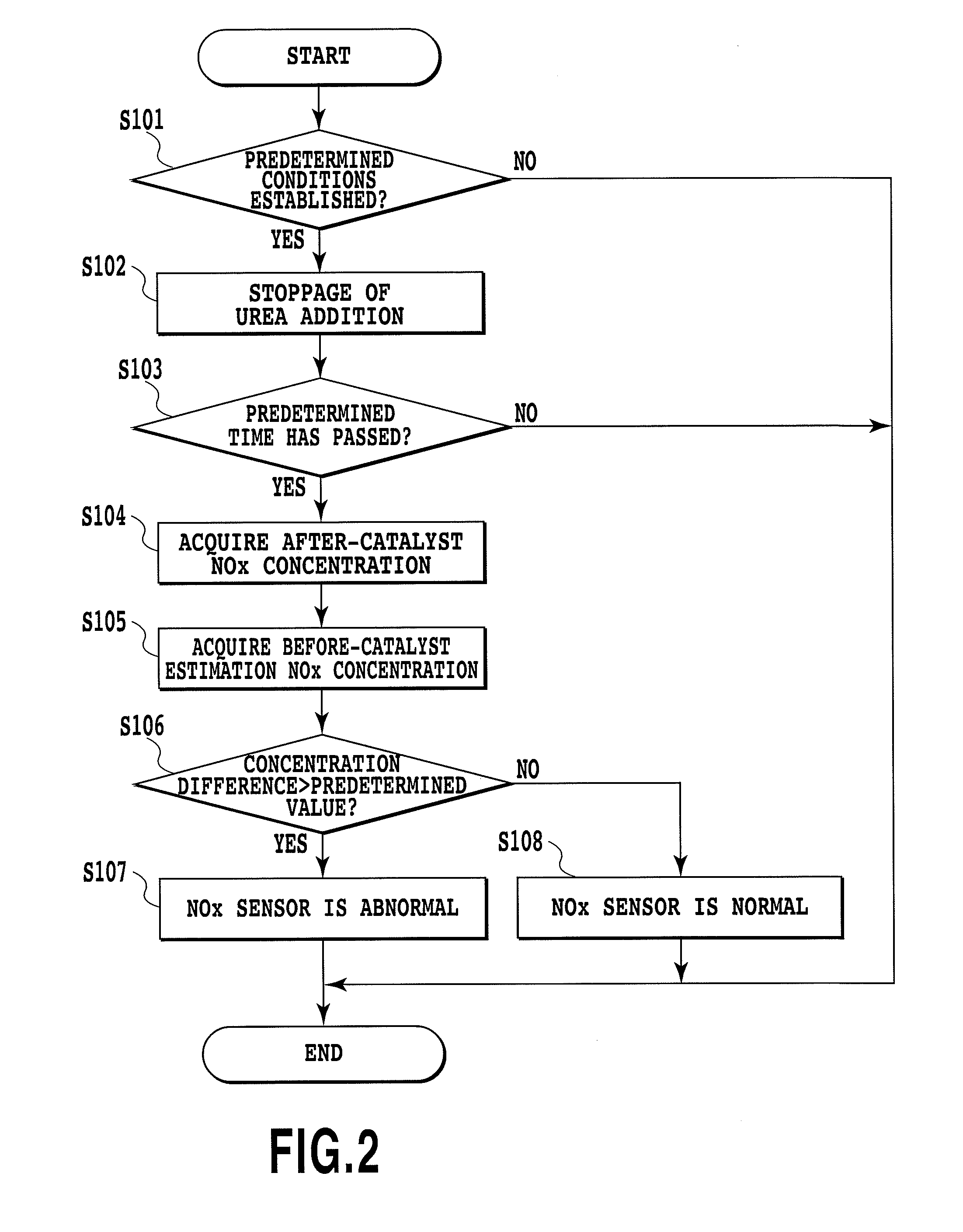
[0092]FIG. 2 shows the abnormality diagnosis processing. The shown routine is repeatedly carried out by the ECU 100 with a predetermined cycle (e.g., 16 msec).

[0093]In the first step S101, whether predetermined conditions suitable for performing the abnormality diagnosis of the after-catalyst NOx sensor 50 are established or not is determined. For example, when all conditions of (a) the after-catalyst NOx sensor 50 reaches an active temperature, (b) the engine 10 is in a steady operation condition, and (c) the warm-up operation of the engine 10 is completed are satisfied, it means that the conditions are established. It is noted that, regarding the condition (b), the engine 10 can be recognized as being in a steady operation when a variation amount of the intake air amount detected by the air flowmeter 22 for example is within fixed values. Another condition (d) where the NOx catalyst 34 has a catalyst temperature equal to or higher than a predetermined minimum active temperature (e...

second embodiment

[0102]Next, the following section will describe abnormality diagnosis processing with reference to FIG. 3. The routine shown in FIG. 3 is also repeatedly executed by the ECU 100 at every predetermined cycle (e.g., 16 msec).

[0103]In the first step S201, it is determined whether predetermined conditions suitable for performing the abnormality diagnosis for the after-catalyst NOx sensor 50 are established or not. The conditions here are different from those in the step S101 in that the two conditions of the condition (a) in which the after-catalyst NOx sensor 50 reaches an active temperature and the condition (b) in which the engine 10 is in an steady operation condition are established for example. When it is determined that the predetermined conditions are not established, this routine is completed.

[0104]When the predetermined conditions are established on the other hand, it is determined in the step S202 whether urea addition is being stopped or not. The stoppage operation is a stop...

third embodiment

[0108]Next, the following section will describe the abnormality diagnosis processing with reference to FIG. 4. The routine shown in FIG. 4 is also repeatedly executed by the ECU 100 at every predetermined cycle (e.g., 16 msec).

[0109]In the first step S301, whether predetermined conditions suitable for performing the abnormality diagnosis of the after-catalyst NOx sensor 50 are established or not is determined as in the step S101. When it is determined that the predetermined conditions are not established, this routine is completed.

[0110]When it is determined that the predetermined conditions are established on the other hand, it is determined in the step S302 whether the current engine operating condition is an idling operation or not.

[0111]Specifically, if urea addition is stopped for abnormality diagnosis, the NOx catalyst 34 cannot reduce NOx and NOx is discharged to the downstream side of the NOx catalyst 34, thus undesirably causing a deteriorated emission. However, during an i...


PUM


Abstract

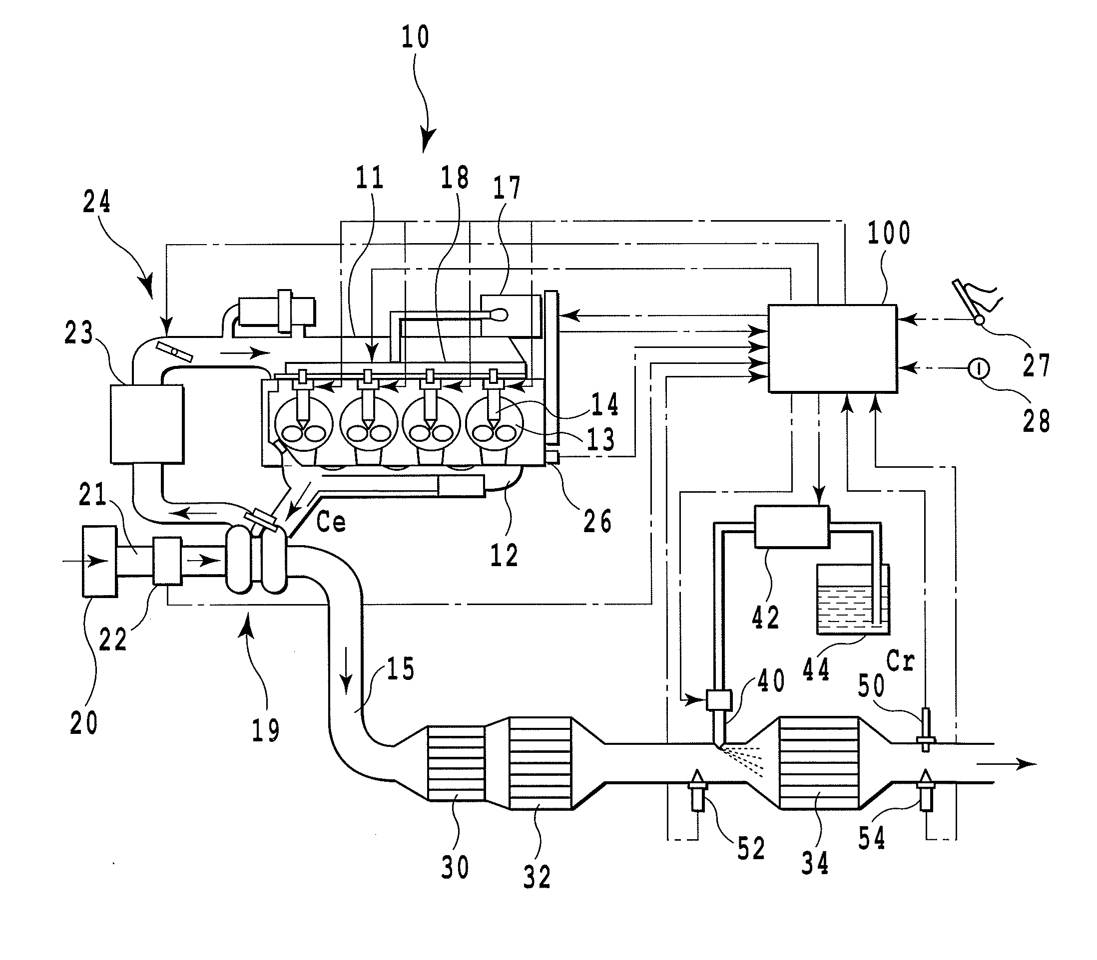
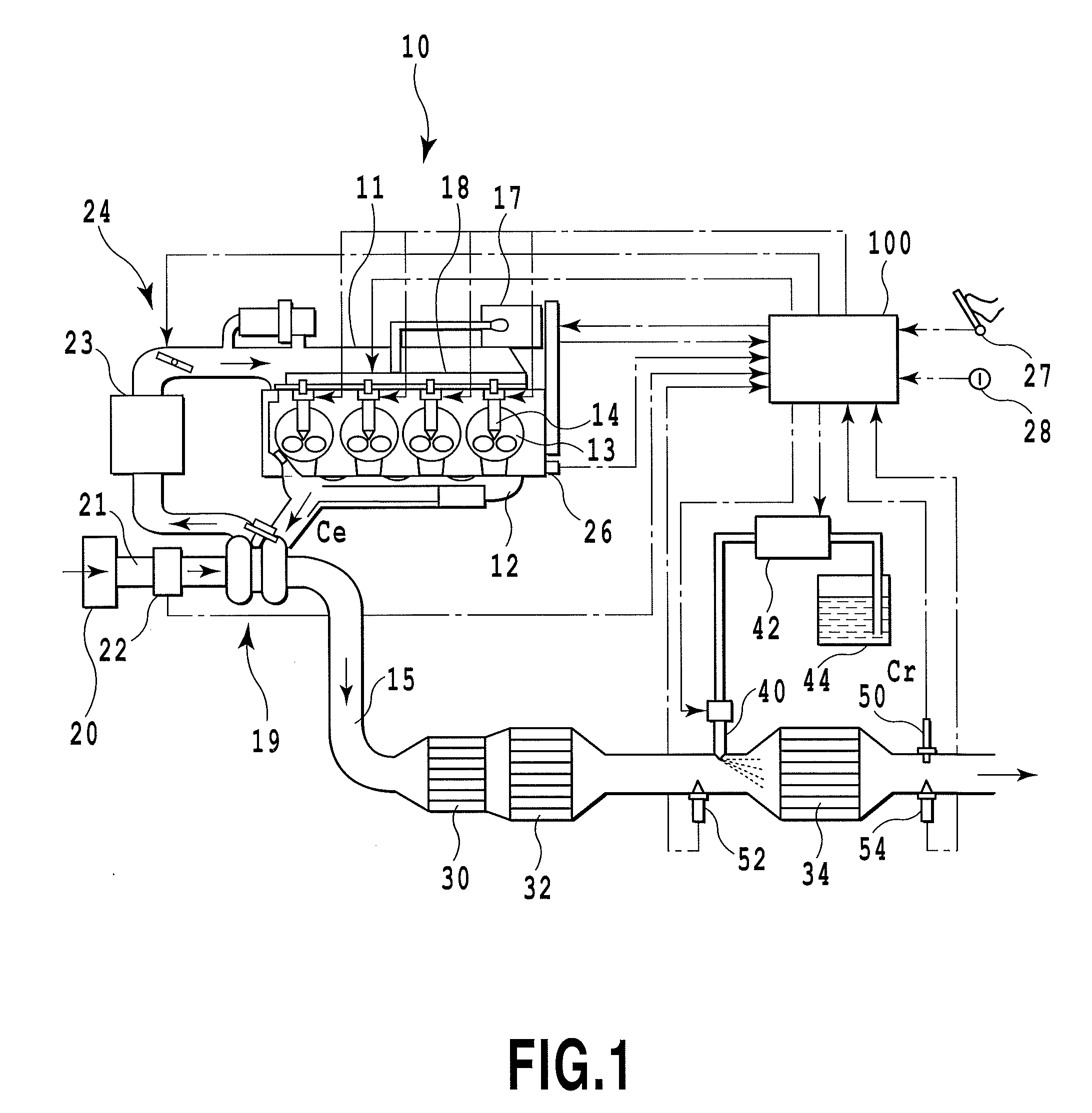
An exhaust passage (15) of an internal-combustion engine (10) includes a selective reduction NOx catalyst (34) and an after-catalyst NOx sensor (50) for detecting a NOx concentration Cr at the downstream thereof. Reducing agent is selectively added from an addition valve (40) to the NOx catalyst. A NOx concentration Ce at the upstream side of the NOx catalyst is detected or estimated. NOx concentrations Cr and Ce before and after the NOx catalyst, which were detected or estimated during the stoppage of an addition of the reducing agent, are compared to each other to thereby determine an abnormality of the after-catalyst NOx sensor (50). An abnormality diagnosis is executed while the addition of reducing agent is being stopped to remove an influence by the NOx catalyst.

Description

TECHNICAL FIELD[0001]The present invention relates to an apparatus and a method for an abnormality diagnosis of a NOx sensor. In particular, the present invention relates to an apparatus and a method for an abnormality diagnosis for a NOx sensor provided at the downstream of a selective reduction NOx catalyst.BACKGROUND ART[0002]Generally, as an exhaust purification apparatus provided in an exhaust system of an internal-combustion engine such as a diesel engine, a NOx catalyst has been known that is for purifying the NOx (nitrogen oxide) included in exhaust gas. Regarding this NOx catalyst, various types of NOx catalysts have been known. Among them, a selective reduction NOx catalyst has been known for which an addition of reducing agent is used to continuously reduce and remove NOx. As reducing agent, urea has been known. Typically, urea aqueous solution is injected and supplied to the exhaust gas at upstream-side of the catalyst and heat receipt from exhaust gas or catalyst genera...

Claims


Application Information

Patent Timeline
Patent Type & Authority Applications(United States)
IPC IPC(8): G01M15/10
CPCF01N3/2066F01N2550/00F01N2560/026F02D41/0275Y02T10/40F02D41/1461F02D41/1463F02D41/222F02D41/146F02D41/1441
Inventor SAWADA, HIROSHISHIBATA, DAISUKE
Owner TOYOTA JIDOSHA KK
Learn More