
Multiple Processes Sharing a Single Infiniband Connection

a technology of infiniband connection and multiple processes, applied in the field of clusters, can solve the problems of large number of send and receive queue structures required per node, large amount of add-ons, and storage space required for qps is not available for application use, so as to improve network performance, reduce system cost, and improve compute performance

Active Publication Date: 2010-12-30
ORACLE INT CORP
View PDF26 Cites 11 Cited by
  • Summary
  • Abstract
  • Description
  • Claims
  • Application Information

AI Technical Summary

Benefits of technology

[0015]Embodiments of the invention relate to sending messages across Infiniband (IB) networks using shared Queue Pair (QP) connections. Embodiments of the invention may have improved network performance, improved compute performance, may have reduced system cost and may be better able to support future system configurations.
[0018]The association of a set of addresses with a transfer process may involve mapping the addresses into an address space that is accessible to the transfer process and is inaccessible to other transfer processes. This feature may provide security for the system and may prevent rogue or buggy software from making unwanted accesses or sending unwanted messages or disrupting the compute node or disrupting a networked group of computers.
[0020]Also, a message command may contain completion queue select data. This information may allow each process that uses a shared QP to specify a completion queue for messages sent by that process. For multiple processes that share a QP, this allows each process to avoid having to share a completion queue. A compute node, having successfully completed the reception of a message, may (if so configured) send an acknowledgement to the sending node. The reception of such an acknowledgement can be the trigger for the placing of a completion record in an appropriate send completion queue. Note that a single completion queue can be used to track both send and receive completions.
[0023]The generation of a message may comprise placing receive queue information in the message. This information may allow transfer processes that use a shared QP for sending to send messages to the same destination QP but to different receive queues. When the message is received at a remote node, the receive queue information in the message may be used to select an appropriate receive queue, and then the payload of the message can be deposited in that selected queue. Since QPs may also be shared by receive processes, this scheme allows multiple receive processes to share a QP but avoid having to share the same receive queue. So, for example, two messages may be received across the same QP connection (sharing the same QP at the receive node) but the messages may be picked up by different receive processes. One message may be picked up by a receive process from a receive queue and the other message may be picked up by another receive process from another receive queue.

Problems solved by technology

The large number of send and receive queue structures required per node is a problem especially on multi-core systems.
First, each QP requires some storage space and this space, multiplied by the number of queue pairs per node, may add up to a significant amount.
This storage space required for QPs is not available for application use.
When QP state information is not held in the adapter and a request arrives associated with that QP, the network adapter responds by loading the state information from memory, adding to overhead and latency.
The more queue pairs there are, then the more often the adapter needs to access memory and the higher the overhead.
Third, the IB specification limits the number of QPs per adapter to 16 million.
As system scale increases and the number of cores per chip grows, there is the danger that this limit will be exceeded in the near future.

Method used


Image

  • Multiple Processes Sharing a Single Infiniband Connection
  • Multiple Processes Sharing a Single Infiniband Connection
  • Multiple Processes Sharing a Single Infiniband Connection

Examples


Embodiment Construction

Definitions

[0040]Compute Node—refers to a computer system having a processor (or CPU) and memory. A Compute Node may have a single processor (which may be single core or multi-core) or may have a plurality of processors. One example of a Compute Node is a blade server.

[0041]Local Node—refers to the Compute Node corresponding to a local reference. For example, the Compute Node associated with a particular CPU would be the CPU's local node.

[0042]Network Fabric—refers to a network or interconnect for connecting multiple Compute Nodes.

[0043]Compute Node Interface Device (or “Network Adaptor”)—refers to an interface for coupling a Compute Node to a Network (or Network Fabric).

[0044]Remote Location—refers to a location on another machine on a network.

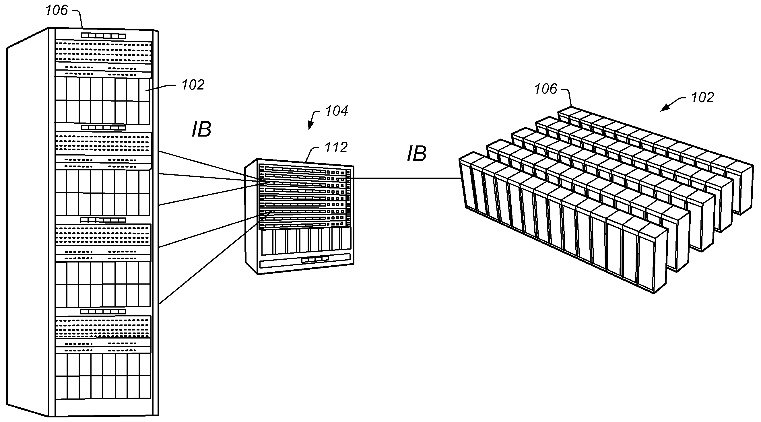
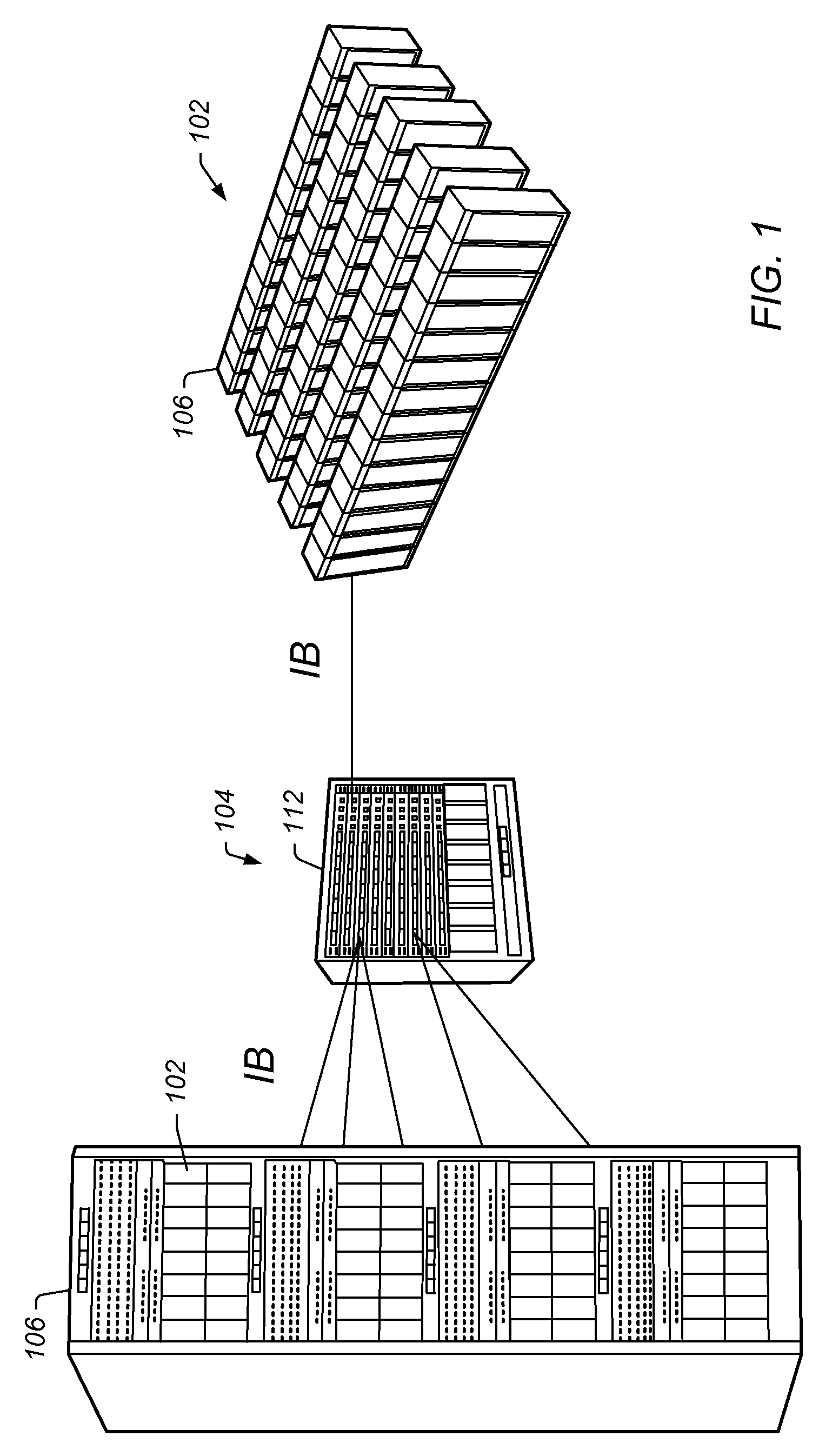
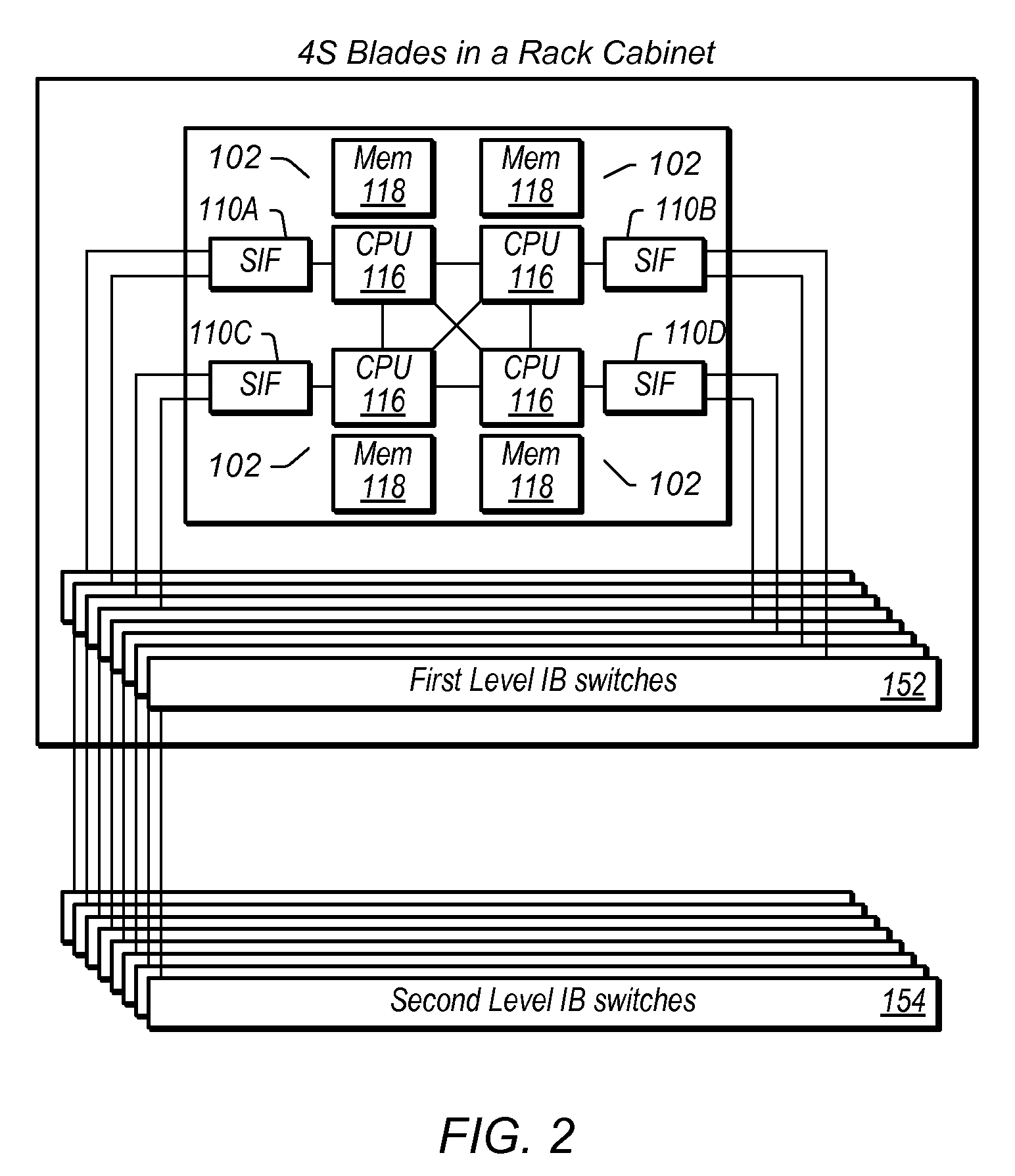
[0045]FIG. 1 illustrates an exemplary cluster system according to one embodiment of the invention. As shown, the system may comprise a plurality of computer systems or compute nodes 102 that are connected together by an interconnect 104. The ...


PUM


Abstract

A compute node with multiple transfer processes that share an Infiniband connection to send and receive messages across a network. Transfer processes are first associated with an Infiniband queue pair (QP) connection. Then send message commands associated with a transfer process are issued. This causes an Infiniband message to be generated and sent, via the QP connection, to a remote compute node corresponding to the QP. Send message commands associated with another process are also issued. This causes another Infiniband message to be generated and sent, via the same QP connection, to the same remote compute node. As mentioned, multiple processes may receive network messages received via a shared QP connection. A transfer process on a receiving compute node receives a network message through a QP connection using a receive queue. A second transfer process receives another message through the same QP connection using another receive queue.

Description

FIELD OF THE INVENTION[0001]The present disclosure relates generally to clusters, and more particularly to a method for multiple processes to share a single Infiniband connection.DESCRIPTION OF THE RELATED ART[0002]A cluster generally refers to a group of computers that have been linked or interconnected to operate closely together, such that in many respects they form a single computer. Large clusters can comprise thousands of individual computer systems that have been linked together. The components (e.g., individual computers or “compute nodes”) of a cluster are often connected to each other through local area networks via network adapters. Clusters generally provide greatly improved performance and / or availability over that provided by a single computer. A cluster is also typically more cost-effective than a single computer of comparable speed or availability.[0003]A cluster generally comprises a plurality of compute nodes (e.g., servers) and the “interconnect” between these com...

Claims


Application Information

Patent Timeline
IPC IPC(8): H04L12/56H04L47/629
CPCH04L47/629H04L47/621
Inventor JOHNSEN, BJORN DAGSUGUMAR, RABIN A.TORUDBAKKEN, OLA
Owner ORACLE INT CORP
Learn More