
Spin Torque Oscillator Sensor

a technology of oscillator and spin torque, which is applied in the field of magnetic heads, can solve the problems of inability to distinguish signals from individual sensor elements, inability to provide individual source and drain leads for each sensor, and inability to use common lead layers to achieve the effect of saving immense space on the head, reducing signal noise, and increasing data density

Active Publication Date: 2010-12-30
WESTERN DIGITAL TECH INC
View PDF27 Cites 45 Cited by
  • Summary
  • Abstract
  • Description
  • Claims
  • Application Information

AI Technical Summary

Benefits of technology

[0009]The present invention can also include a multi-sensor array in which a plurality of individual sensor elements are arranged in an array and are connected to common leads. The individual sensor elements can be constructed so that they have different natural oscillation frequencies. Because these natural frequencies are different, the circuitry connected with the sensors can be constructed to distinguish the signals from the various individual sensors even if they are connected with the circuitry via a common lead. This advantageously allows a single pair of leads to be used for a plurality of sensor elements, saving immense space on the head and making such a multi-sensor array manufacturable and practical. This use of common lead layers would not be possible using a conventional sensor such as a GMR or TMR sensor, because it would be impossible to distinguish the signals from the individual sensor elements. Further, providing individual source and drain leads for each sensor is not practical because in the small volume required for parallel detection of small recording bits there is insufficient room to place and route the leads.
[0010]In such a multi-sensor array, the individual sensor elements can be connected in parallel or in series, or both. The use of such a multi-sensor array advantageously allows for greatly increased data density, because it makes it possible to read and cancel out signals from adjacent data. This can be used to greatly decrease signal noise or supply a position error signal to help maintain proper positioning of the head.

Problems solved by technology

This use of common lead layers would not be possible using a conventional sensor such as a GMR or TMR sensor, because it would be impossible to distinguish the signals from the individual sensor elements.
Further, providing individual source and drain leads for each sensor is not practical because in the small volume required for parallel detection of small recording bits there is insufficient room to place and route the leads.

Method used


Image

  • Spin Torque Oscillator Sensor
  • Spin Torque Oscillator Sensor
  • Spin Torque Oscillator Sensor

Examples


Embodiment Construction

[0022]The following description is of the best embodiments presently contemplated for carrying out this invention. This description is made for the purpose of illustrating the general principles of this invention and is not meant to limit the inventive concepts claimed herein.

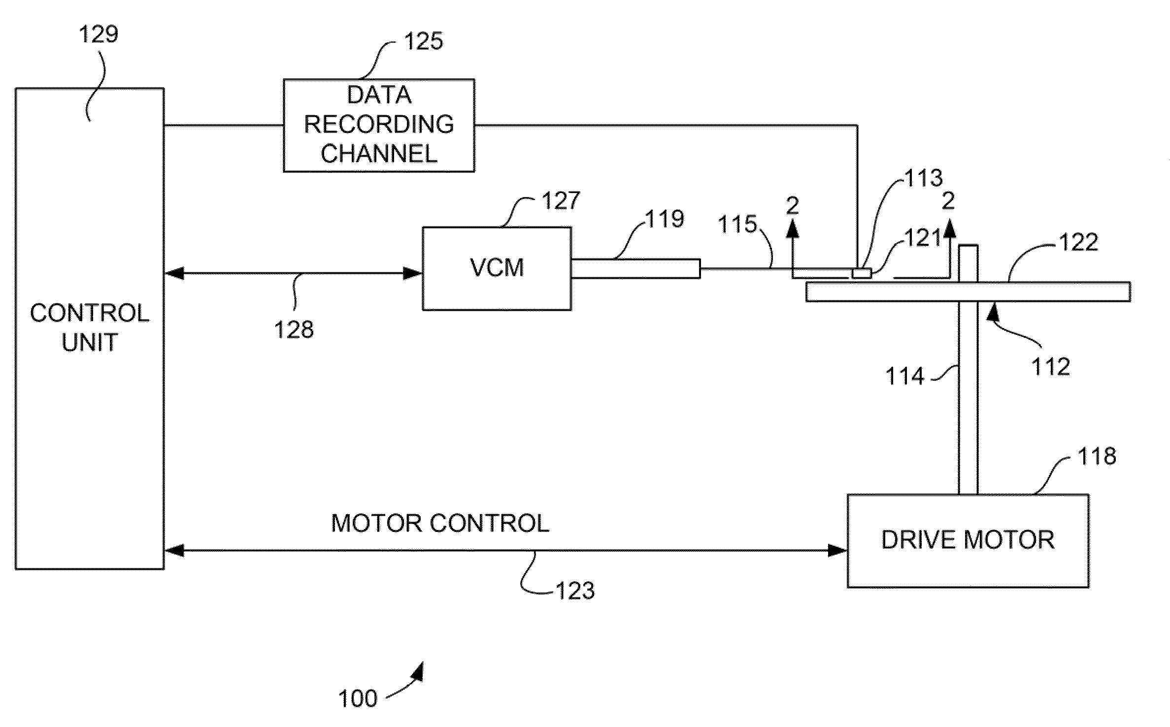
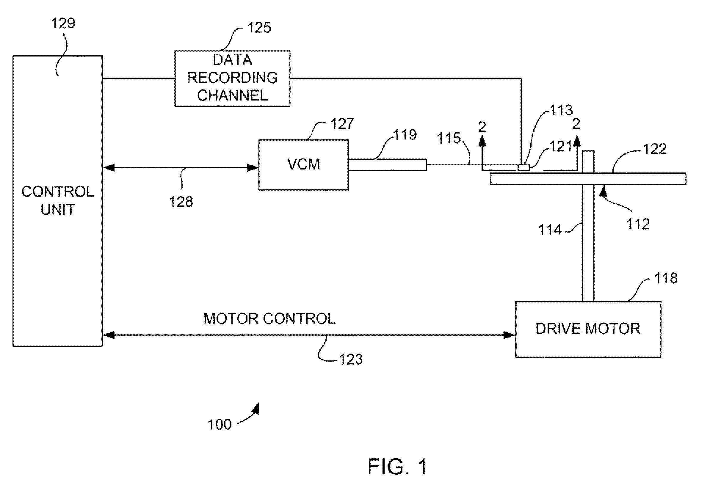
[0023]Referring now to FIG. 1, there is shown a disk drive 100 embodying this invention. As shown in FIG. 1, at least one rotatable magnetic disk 112 is supported on a spindle 114 and rotated by a disk drive motor 118. The magnetic recording on each disk is in the form of annular patterns of concentric data tracks (not shown) on the magnetic disk 112.

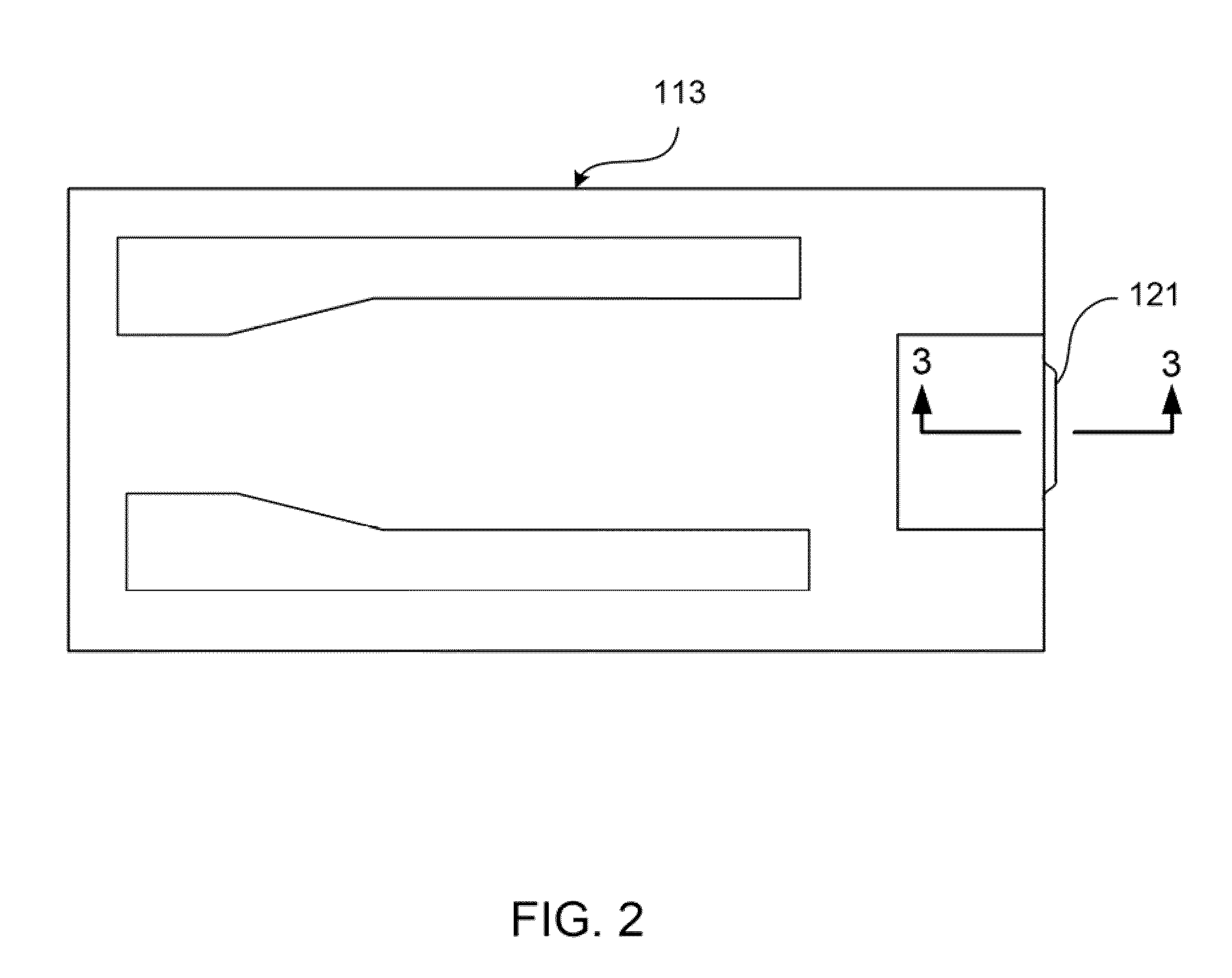
[0024]At least one slider 113 is positioned near the magnetic disk 112, each slider 113 supporting one or more magnetic head assemblies 121. As the magnetic disk rotates, slider 113 moves radially in and out over the disk surface 122 so that the magnetic head assembly 121 may access different tracks of the magnetic disk where desired data are written. Each slider 1...


PUM

PropertyMeasurementUnit
thicknessaaaaaaaaaa
frequencyaaaaaaaaaa
frequencyaaaaaaaaaa

Abstract

A spin torque oscillation magnetoresistive sensor for measuring a magnetic field. The sensor uses a change in precessional oscillation frequency of a magnetization of a magnetic layer to determine the magnitude of a magnetic field. The sensor can include a magnetic free layer, a magnetic pinned layer and a non-magnetic layer sandwiched therebetween. Circuitry is connected with these layers to induce an electrical current through the layers. Spin polarization of electrons traveling through the device causes a spin torque induced precession of the magnetization of one or more of the layers. The frequency of this oscillation modulates in response to a magnetic field. The modulation of the oscillation frequency can be measured to detect the presence of the magnetic field, and determine its magnitude.

Description

FIELD OF THE INVENTION[0001]The present invention relates to magnetic heads for data recording, and more particularly to a sensor that uses spin torque induced magnetic oscillation variation to detect a magnetic field.BACKGROUND OF THE INVENTION[0002]The heart of a computer's long term memory is an assembly that is referred to as a magnetic hard disk drive. The magnetic hard disk drive includes a rotating magnetic disk, write and read heads that are suspended by a suspension arm adjacent to a surface of the rotating magnetic disk and an actuator that swings the suspension arm to place the read and write heads over selected circular tracks on the rotating disk. The read and write heads are directly located on a slider that has an air bearing surface (ABS). The suspension arm biases the slider toward the surface of the disk, and when the disk rotates, air adjacent to the disk moves along with the surface of the disk. The slider flies over the surface of the disk on a cushion of this m...

Claims


Application Information

Patent Timeline
Patent Type & Authority Applications(United States)
IPC IPC(8): G11B27/36G11B5/33
CPCB82Y25/00G01R33/093G01R33/1284G11B5/3903H01F10/329H01F10/3254H01F10/3268H01L43/08H01F10/3286G11B2005/0002G11B2005/0016H10N50/10
Inventor BRAGANCA, PATRICK MESQUITAGURNEY, BRUCE ALVINWILSON, BRUCE ALEXANDER
Owner WESTERN DIGITAL TECH INC
Learn More