
Shock-absorbing fence

a technology of shock absorption and guard net, which is applied in the direction of wire networks, building types, construction, etc., can solve the problems of sacrificing protection performance, difficult to implement costly countermeasures, and inability to trap falling rocks, so as to achieve less deflection and deformation of the guard net

Inactive Publication Date: 2010-12-30
PROTEC ENG
View PDF5 Cites 9 Cited by
  • Summary
  • Abstract
  • Description
  • Claims
  • Application Information

AI Technical Summary

Benefits of technology

[0022](1) When hit by falling rocks, the safety net moves along with the guard net stretched between the main posts, thereby to ensure entrapment of the falling rocks.
[0023](2) In case of rockfall, the safety net extends in a manner following deflection and deformation of the guard net while maintaining a gap below the guard net closed, thereby to reduce the change of the effective height of the guard net. In this way, falling rocks are prevented from slipping through or jumping over the safety net, and the capability to trap falling rocks is greatly improved.
[0024](3) The section where the safety net is attached to the guard net is reinforced as the double-layered structure, thereby to enhance the safety reliability of the shock-absorbing fence.
[0025](4) When hit by falling rocks, the amount of the impact energy absorbed accompanying the weight shift of the guard net increases by the weight of the safety net, and the amount of the impact energy absorbed also increases by the friction resistance between the hillside slope and safety net.
[0026]As a result, there is less deflection and deformation of the guard net than before.
[0027]In particular, it is suitable for installation in locations adjacent to road infrastructure, railroad facility, and housing, for example, where the amount of deflection and deformation of the guard net is strictly limited.

Problems solved by technology

As a result, in case that rockfalls occur in a repetitive manner, rocks from subsequent rockfalls can slip through a gap wide open between the bottom end of the net and the ground, and the rocks may jump over the net, posing problems in its capability to trap falling rocks.
However, in light of the current severe economic environment, it is difficult to implement costly countermeasures as mentioned above, and for this reason, it is much needed to propose a shock-absorbing fence whose installation costs can be lowered without sacrificing the protection performance.

Method used


Image

  • Shock-absorbing fence
  • Shock-absorbing fence
  • Shock-absorbing fence

Examples


Embodiment Construction

[0038]Hereinafter, an embodiment of the present invention will be described with reference to the accompanying drawings.

(1) Entire Configuration of a Shock-absorbing Fence

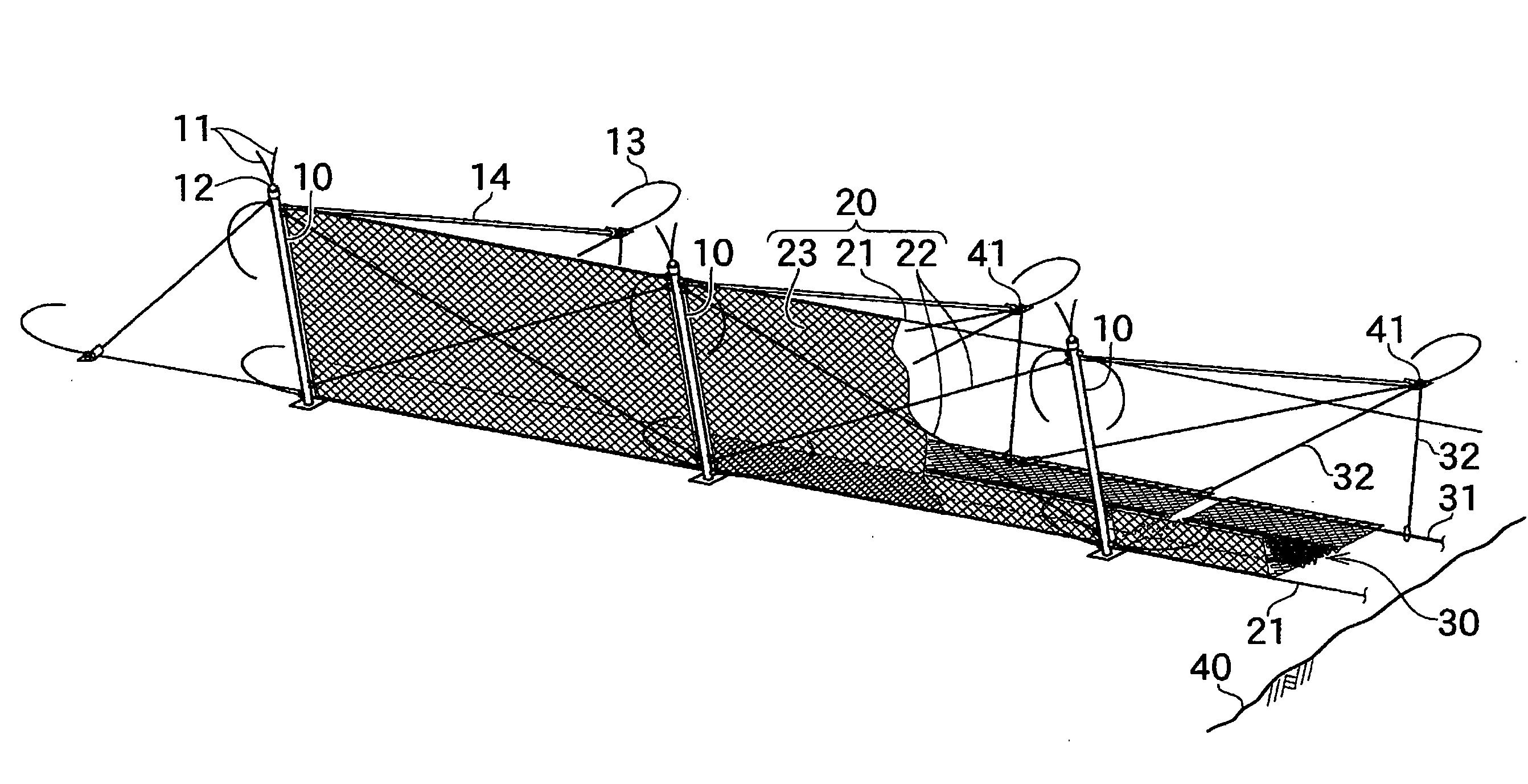
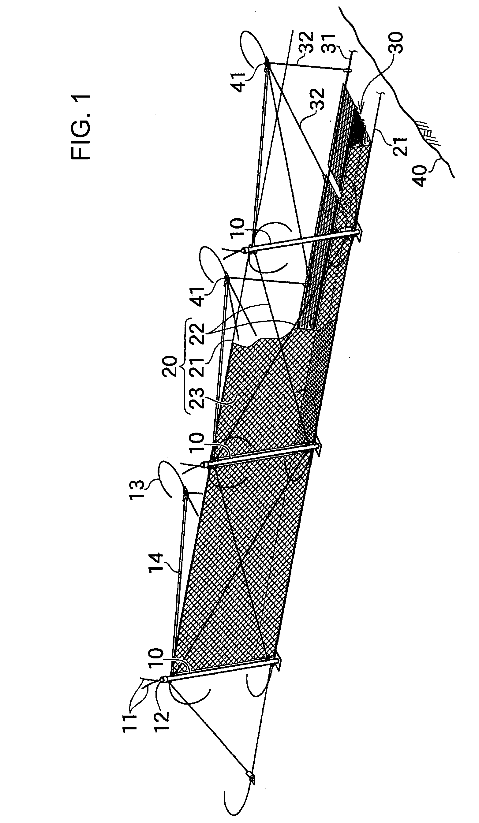
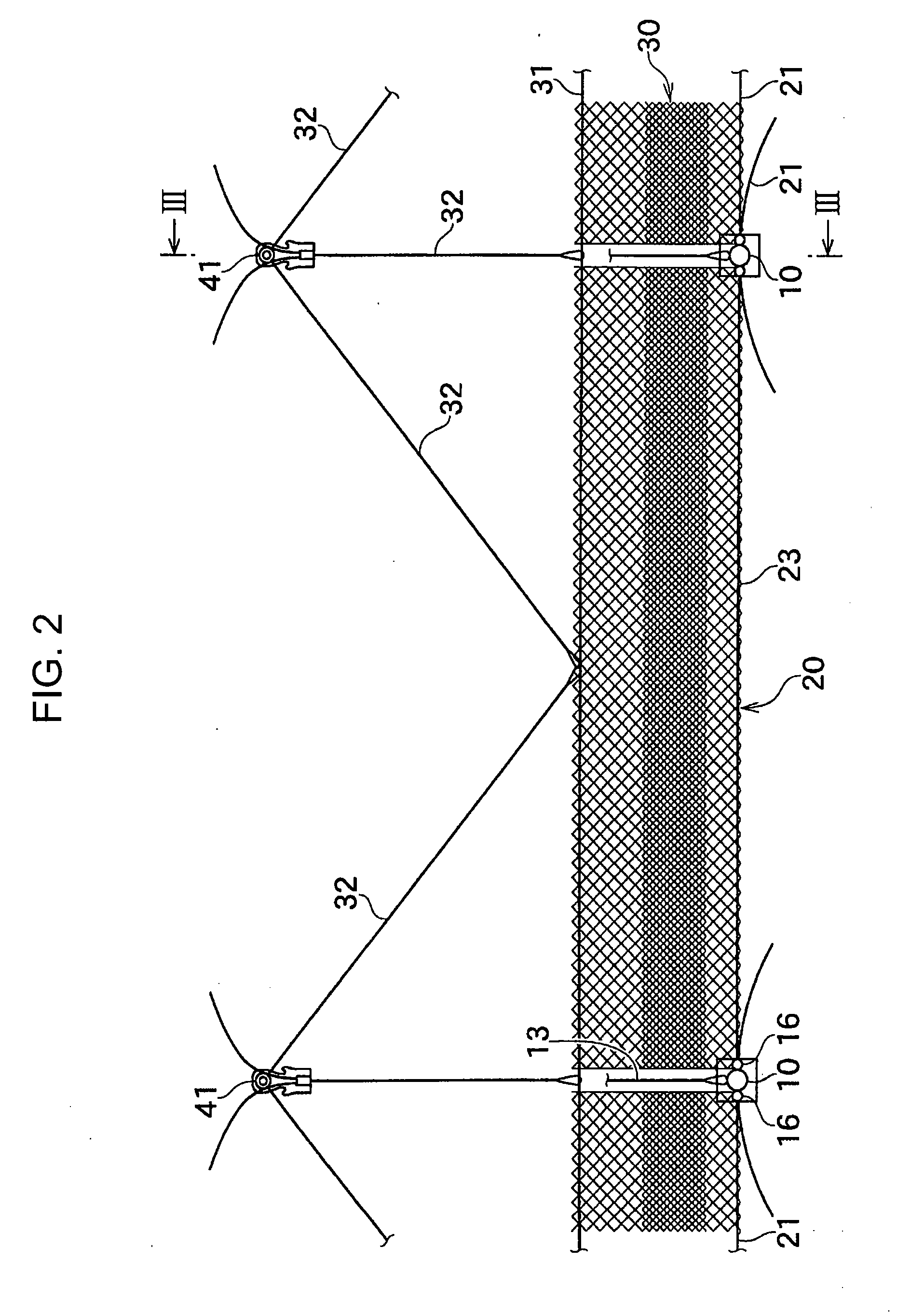
[0039]FIGS. 1 and 2 illustrate one example of a shock-absorbing fence according to the embodiment of the present invention.

[0040]It is assumed that the present invention includes a shock-absorbing fence equipped with main posts 10 provided to stand at predetermined intervals and a guard net 20 stretched across the main posts 10. Moreover, the present invention is provided with a safety net 30 installed between the skirt of the guard net 20 and a slope 40 as means for reducing the change of the effective height of the guard net 20.

[0041]The shock-absorbing fence in this embodiment is only exemplary and it can be applied to a variety of well-known shock-absorbing fences as long as it is equipped with protective nets.

[0042]Hereinafter, the configuration of a shock-absorbing fence according to an embodiment of the pres...


PUM


Abstract

A shock-absorbing fence comprises: a guard net provided in a stretched state between main posts provided to stand at a predetermined interval; a safety net attached between a skirt of the guard net and a ground; and a member joining an upper rim of the safety net to the skirt of the guard net as well as securing a lower rim of the safety net to the ground, the member including a horizontal support rope member provided along the lower rim of the safety net and a plurality of hillside support rope members connecting between a plurality of points of the horizontal support rope member and a plurality of hillside anchors, the safety net being allowed to deform in an extended manner following deflection and deformation of the guard net, while maintaining a gap below the guard net in a closed state, in case of rockfall.

Description

CROSS REFERENCE TO RELATED APPLICATIONS[0001]This is a continuation application of International Patent Application No. PCT / JP2008 / 000943 filed Apr. 10, 2008 claiming priority upon Japanese Patent Application No. 2008-026345 filed Feb. 6, 2008, of which full contents are incorporated herein by reference.BACKGROUND[0002]1. Technical Field[0003]The present invention relates to a shock-absorbing fence that absorbs impacts of falling objects such as falling rocks and soil, and in particular relates to a shock-absorbing fence that has the improved capability to capture falling rocks.[0004]2. Description of the Related Art[0005]In Japanese Patent Application Laid-Open Publication No. H7-197423, there is disclosed a shock-absorbing fence that includes: tubular main posts built in vertical holes bored at intervals on a hillside slope to be provided in a standing state; and a net formed of metallic mesh provided in a stretched state on each of the tubular main posts along with cables at a pl...

Claims


Application Information

Patent Timeline
Patent Type & Authority Applications(United States)
IPC IPC(8): E04H17/16
CPCE01F7/045
Inventor NISHITA, YOICHIFUJII, TOMOHIRONOMURA, TOSHIMITSU
Owner PROTEC ENG
Learn More