
Steering column for a motor vehicle

a technology for steering columns and motor vehicles, applied in the direction of steering columns, steering parts, vehicle components, etc., can solve the problems of increased safety risk, increased breakaway torque of steering spindles, increased crash level, etc., and achieves low weight, low outlay, and easy mounting

Active Publication Date: 2019-02-21
THYSSENKRUPP PRESTA AG +1
View PDF2 Cites 6 Cited by
  • Summary
  • Abstract
  • Description
  • Claims
  • Application Information

AI Technical Summary

Benefits of technology

The invention is a safety element that prevents excessive deflection of the steering spindle in the event of a crash. It achieves this by forming a radial restriction for the steering spindle within the casing unit. This results in a maximum radial deflection of the steering spindle, preventing damage to the steering column and ensuring safe pushing together of the steering spindle. The safety element is advantageously made from plastic material, being lightweight, cost-effective and easy to install.

Problems solved by technology

The deflection of the steering spindle can lead to the steering shaft not, or only with greatly increased axial force, being pushed into the hollow shaft, as a result of which the axial force required to telescope the steering column, what is known as the crash level, is increased in an uncontrolled manner up to locking of the steering column.
A safety risk arises as a result of this.
It is, however, disadvantageous that the breakaway torque of the steering spindle is increased by the additional bearing as a result of the bearing friction.
In particular, the third bearing is, as a result of the overdetermined arrangement between the front and rear bearing, particularly sensitive with respect to tolerances of the steering spindle, and can be impaired in terms of its function or damaged, which can lead to a higher breakaway torque.
The high tolerance requirements further result in a correspondingly high manufacturing and assembly outlay.

Method used


Image

  • Steering column for a motor vehicle
  • Steering column for a motor vehicle
  • Steering column for a motor vehicle

Examples


Embodiment Construction

[0046]Identical parts are always provided with the same reference numbers in the various figures and are also therefore respectively only generally cited or mentioned once.

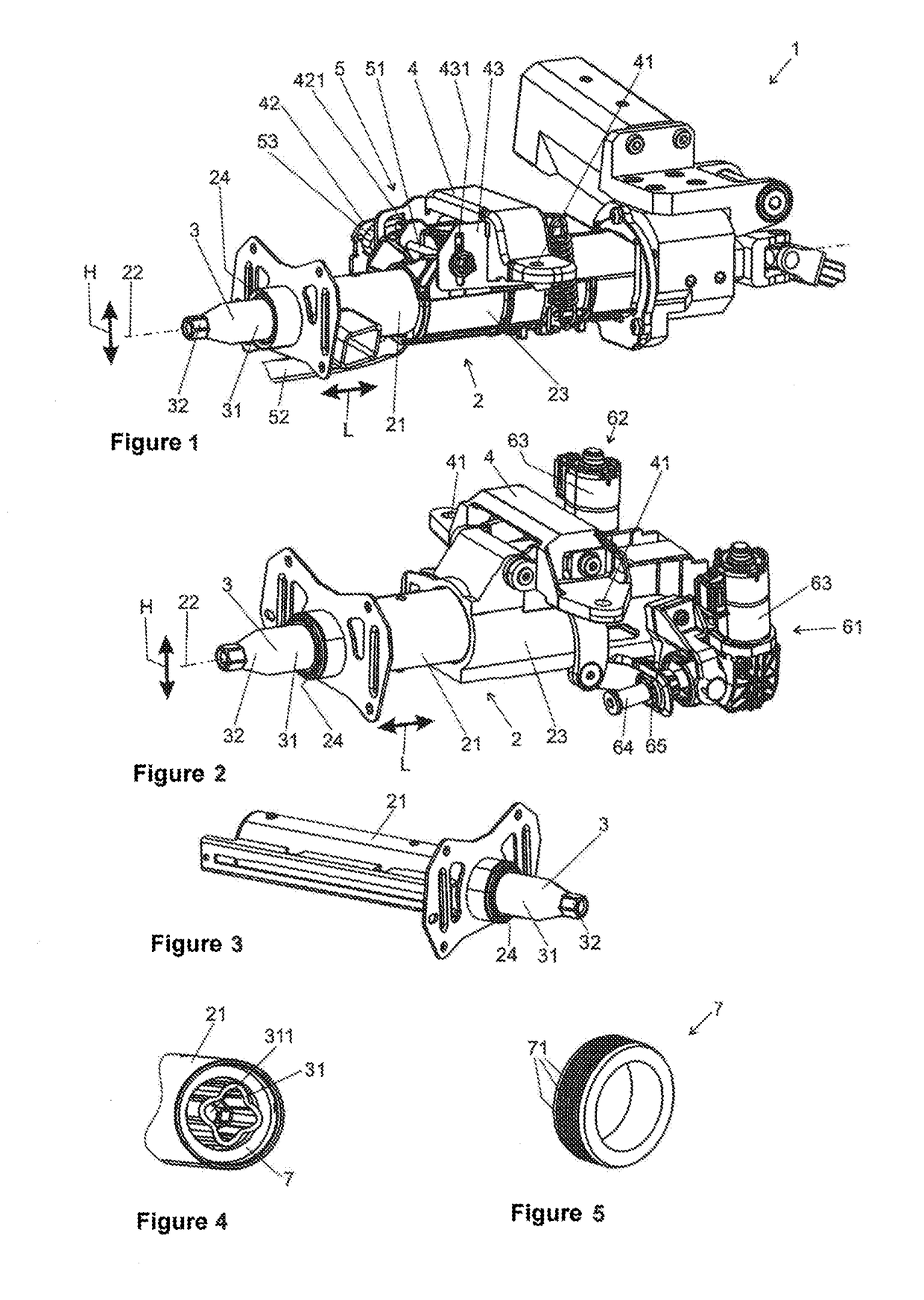
[0047]FIG. 1 shows a perspective view of a steering column 1, wherein the rear end in terms of the direction of travel is directed obliquely to the left in front of the observer.

[0048]Steering column 1 comprises a casing unit 2 with an inner casing tube 21 which is received coaxially in relation to a longitudinal axis 22 in an outer casing tube 23 and is telescopic in longitudinal direction L, which is indicated by the double arrow.

[0049]A steering spindle 3 is mounted rotatably in casing unit 2 coaxially about longitudinal axis 22. Steering spindle 3 comprises a hollow shaft 31 which projects to the rear out of inner casing tube 21 and comprises at its end facing the driver a fastening portion 32 for attachment of a steering wheel, not represented.

[0050]A support unit 4 comprises fastening means 41 for fastening ...


PUM


Abstract

A steering column for a motor vehicle includes a case with a steering gear-side end and a steering wheel-side end. The case includes an outer casing tube in which an inner casing tube is arranged telescopically and in which a steering spindle is mounted rotatably about a longitudinal axis. The steering spindle includes a hollow shaft in which a steering shaft is arranged telescopically. The steering spindle is mounted rotatably in a rear bearing in the steering wheel-side end portion. A safety element may be arranged between the steering gear-side end of the case and the rear bearing between the case and the steering spindle, which leaves a circumferential radial safety distance between the case and steering spindle which is smaller than the radial distance between the case and steering spindle outside the safety element between the steering gear-side end of the case and the rear bearing.

Description

PRIOR ART[0001]The invention relates to a steering column for a motor vehicle, comprising a casing unit with a steering gear-side end and a steering wheel-side end, wherein the casing unit comprises an outer casing tube in which an inner casing tube is arranged telescopically, and in which a steering spindle is mounted rotatably about a longitudinal axis, wherein the steering spindle comprises at least in portions a hollow shaft in which a steering shaft is arranged telescopically, and the steering spindle is mounted rotatably in a rear bearing in the steering wheel-side end portion of the casing unit.[0002]In the case of such length-adjustable steering columns, the steering wheel attached to the rear end of the steering spindle in terms of the direction of travel can be positioned in the vehicle interior by a length adjustment in the longitudinal direction, i.e. in the direction of the steering column longitudinal axis, and as a result adapted to the driver position. The adjustabil...

Claims


Application Information

Patent Timeline
Patent Type & Authority Applications(United States)
IPC IPC(8): B62D1/19B62D1/185
CPCB62D1/192B62D1/185
Inventor ANCELIN, MATTHIASSCHNITZER, HIERONYMUSHEEB, TOBIAS
Owner THYSSENKRUPP PRESTA AG
Learn More