
Valence junction fitting

a technology of valve junction and fitting, which is applied in the direction of resiliently-mounted floors, door/window protective devices, walls, etc., can solve the problems of high scrap rate, inability to expect the home installer to have tools, and high cost and labor rate, so as to achieve a more stable or substantial relationship and less deflection of the first member

Inactive Publication Date: 2009-08-18
LEE HAN SEN
View PDF7 Cites 5 Cited by
  • Summary
  • Abstract
  • Description
  • Claims
  • Application Information

AI Technical Summary

Benefits of technology

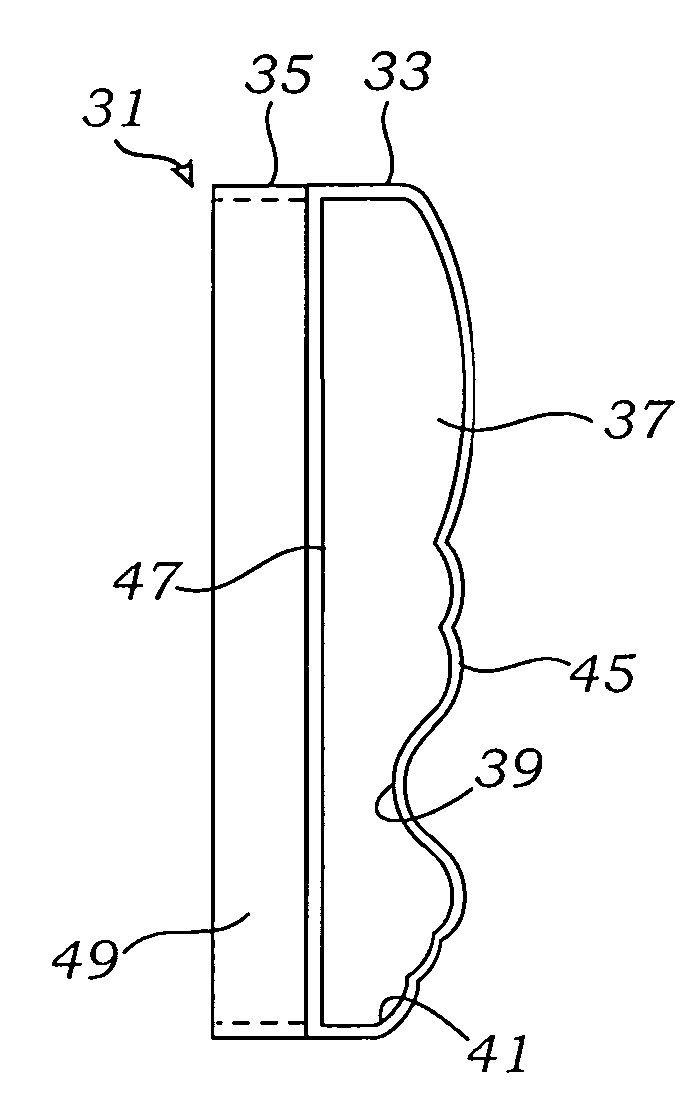
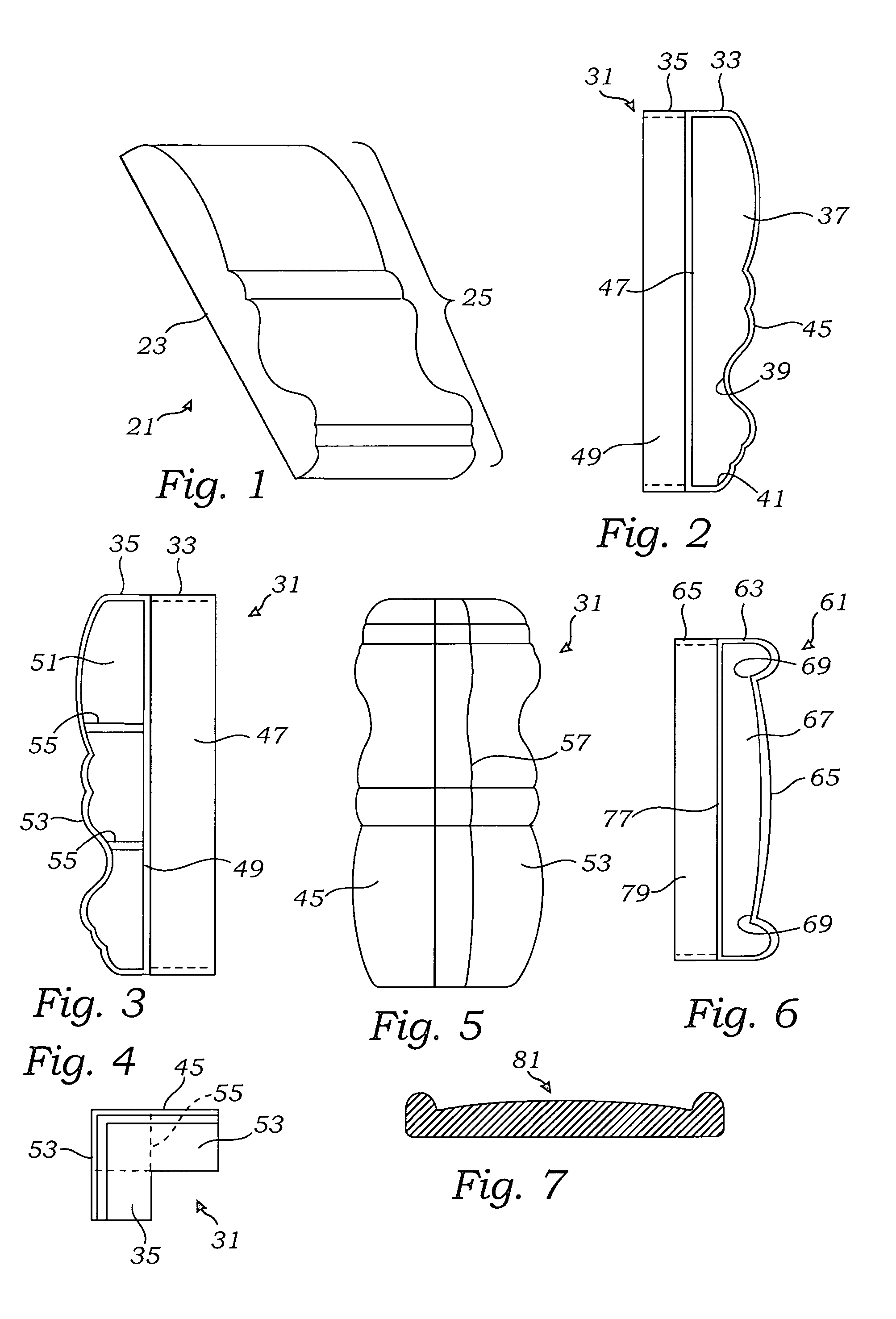
[0008]A specialized angle valence junction fitting forms a joint for connecting two lengths of valence molding. The fitting has a pair of openings directed 90° apart and has an internal shape matching an external shape of the molding utilized. The specialized angle joint may have a color to match or accent two lengths of molding and has an external dimension which is only about 1.5 millimeters greater than the dimension of the molding which it surrounds. Valence junction fitting can have an end edge which is straight, or beveled to imply a more stabilized or substantial relationship to the molding. The fitting can have channels which are uneven to assist in the order of attachment, with the shorter fitting providing the necessity for lesser deflection of a first member to which it is attached in order to interfit with another section of molding, when a shape is being completed. Further, the longer channel can be used to better support a length of molding which is cut slightly short of the target.

Problems solved by technology

Custom installations with high cost and high labor rates have the relative luxury of custom cutting and fitting and significant scrap.
Conversely, for home installation a high scrap rate creates an intolerable rise in cost, and an impossible expectation that the home installer will have the tools necessary to cut and fit the valence members.
A cut also means that a thin, black crack will be left between the two members.
The alternatives to eliminate the crack are associated with further time and effort on the part of the custom installer.
Another problem with valences is the manner of joining of the segments.
Glue can be unsatisfactory and can leave an unsightly appearance.
With these latter two cases, any deviation by the installer can leave a mis-matched angle or mis-matched gap which will require filler, painting, or other space and color correction.
Another problem with the 45° miter cut is the necessity to re-perform this cut for each 90° angle.
Attempted use of any length which is too short or too long will result in corner angles deviating from 90°.
Where the ends are 45° miter cut, even larger gaps will result.
Most cuts are not high precision, and self-installers very likely lack the ability to finely sand the ends to insure a match fit.
Even where precision cut and sanding are present, the use of a 45° sharp end is more susceptible to dents and nicks during cutting.
The production of a sharp edge, especially with the fanciful shape of most valences has the potential to produce even more scrap and wasted time.

Method used


Image

  • Valence junction fitting
  • Valence junction fitting

Examples


Embodiment Construction

[0018]The description and operation of the valence junction fitting of the invention will be best begun with reference to FIG. 1 which illustrates a typical, fairly complex surface detail of an extruded valence 21 which can be used for other purposes. The valence 21 is typically a molding made of wood and having an extruded-type design. By “extruded type” it is meant that it may have a constant cross sectional area and profile. The short section is seen in perspective and is seen to have a flat rear side 23, and a front complex surface 25. The front complex surface 25 includes an undulating up and down pattern across one side of a width of the valence 21.

[0019]The valence 21 is typically made of wood and may be formed by moving a plank through a shaped planer which selectively removes the wood to yield the shape seen in FIG. 1. Valence 21 could also be made of plastic or other material. It is also understood that the constant cross sectional area shown need not extend over the entir...


PUM


Abstract

A specialized angle valence junction fitting forms a joint for connecting two lengths of valence molding. The fitting has a pair of openings angled apart and has an internal shape matching an external shape of the molding utilized. The specialized angle joint may have a color to match or accent two lengths of molding and has an external dimension which is only about 1.5 millimeters greater than the dimension of the molding which it surrounds. Valence junction fitting can have an end edge which is straight, or beveled to imply a more stabilized or substantial relationship to the molding.

Description

FIELD OF THE INVENTION[0001]The present invention relates to an improvement in providing a more customized window covering valence fit while eliminating the need for an exacting miter box with exacting dimensioning and custom installation.BACKGROUND OF THE INVENTION[0002]Valence structures have traditionally been utilized to complete a window treatment. Custom installed valences require ordering and custom cutting of what is typically a linear molding. Of course, non-extruded style valences can be used which have specific decorative patterns or lengths of constant cross sectional area punctuated with an intermittent pattern, such as a flower or the like. Custom installations with high cost and high labor rates have the relative luxury of custom cutting and fitting and significant scrap. For custom installations, a high scrap rate is tolerable both economically and in terms of availability of a large supply of materials. Conversely, for home installation a high scrap rate creates an ...

Claims


Application Information

Patent Timeline
Patent Type & Authority Patents(United States)
IPC IPC(8): E06B9/00
CPCE04F19/0495E04F19/02E04F2019/0454E04F2019/0413
Inventor LEE, HAN-SEN
Owner LEE HAN SEN
Learn More