
Spacecraft afterbody device

Active Publication Date: 2010-12-30
ARIANEGRP SAS
View PDF12 Cites 7 Cited by
  • Summary
  • Abstract
  • Description
  • Claims
  • Application Information

AI Technical Summary

Benefits of technology

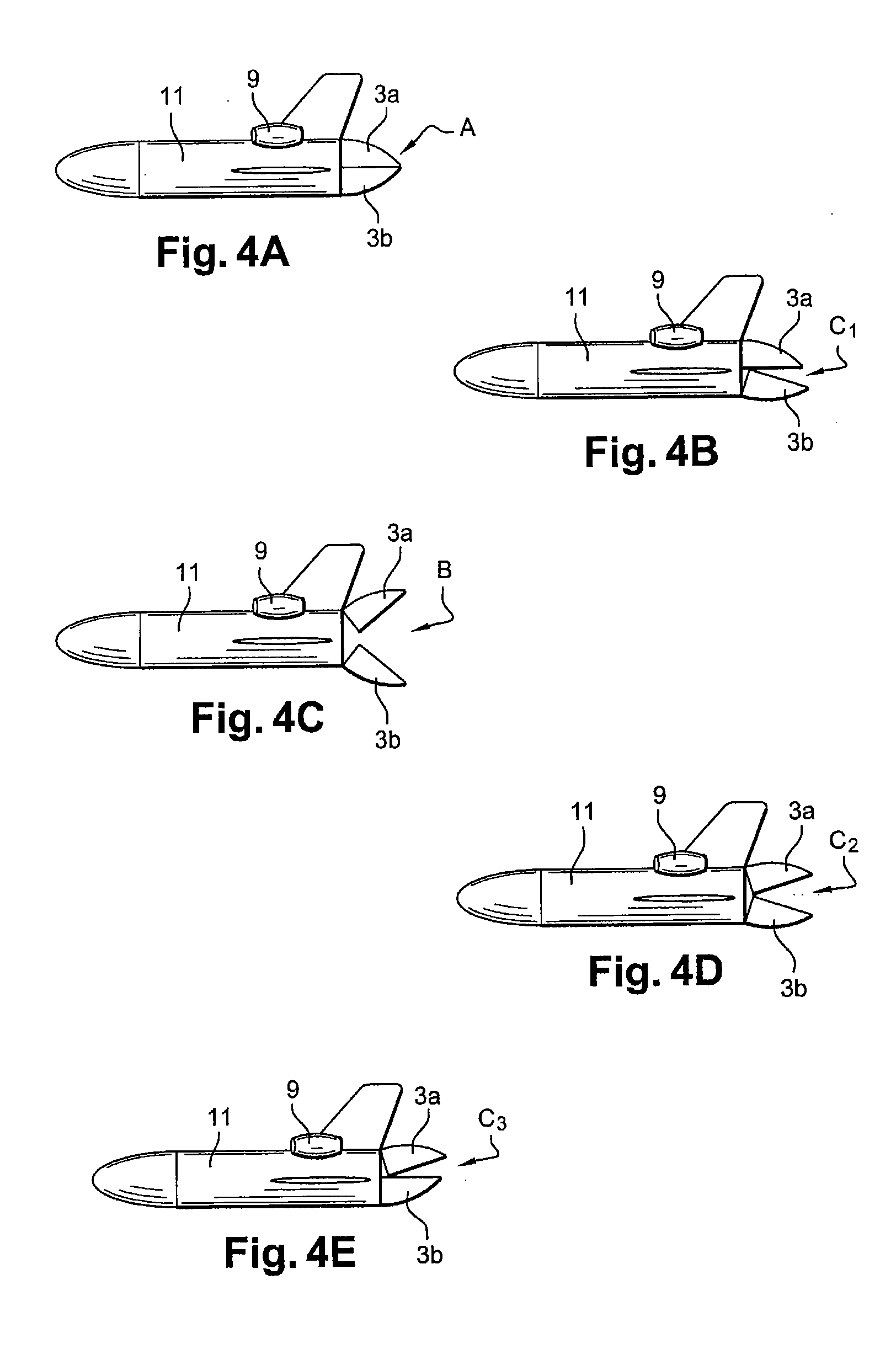
[0025]The device of the invention has the advantage in this case of allowing a simplification and a weight reduction in the flight controls of a space plane since these flight controls no longer need to be designed to carry out the plane's aerodynamic braking.
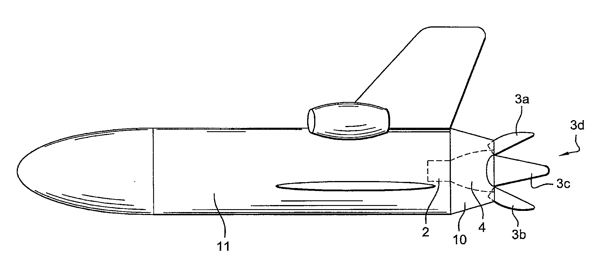
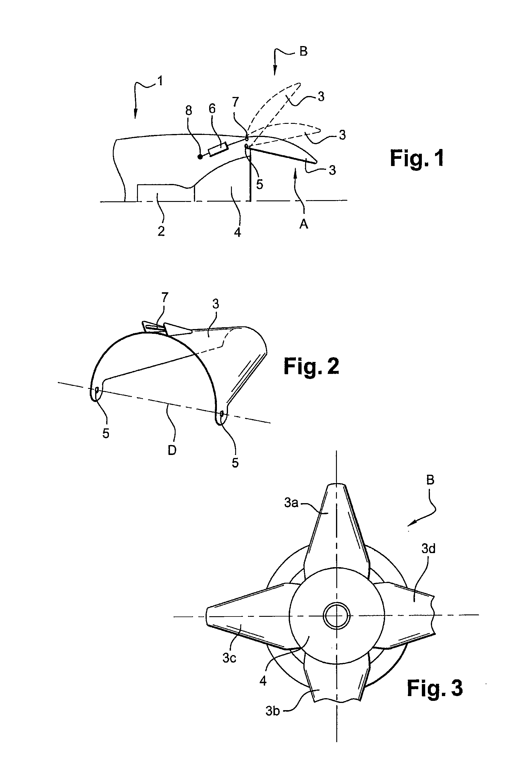
[0026]To achieve this, this invention provides an afterbody device for a spacecraft fitted with at least one rocket engine at the rear of the craft characterized in that it comprises at least one movable cover element designed to take a first position, masking and reducing the vehicle's rear drag, where it prolongs the vehicle's fuselage around at least one part of a rocket engine nozzle of the vehicle and extends beyond the rear of the vehicle's fuselage, and to take a second position fully deployed, increasing the vehicle's aerodynamic drag.

Problems solved by technology

In contrast an unused engine creates an enormous amount of drag (up to one third of the vehicle's total drag).
On the other hand, such a cover cannot be used when this shuttle is launched because it would be necessary to jettison it before igniting the rocket engine, which would entail designing a cumbersome release device ensuring that no debris could damage the shuttle or the jettisonable boosters.
The same would apply to a space plane, for which the jettisoning operation would remain risky.
Similarly, using active fluid-injection devices on a space plane would require the fluid to be carried in the vehicle, which would reduce its payload.
The specific case of a spacecraft designed for atmospheric flight using jet engines and designed for flight outside the atmosphere using a rocket engine leads to contradictory requirements with respect to performance.
In aeronautical-type atmospheric flight, minimal drag is required and therefore in particular as small a cross-section as possible for the rear section, whereas for space flight, a large cross-section for the engine nozzle exhaust is desired, which is detrimental to the reduction of base drag.
The presence of rocket propulsion therefore presents a problem in atmospheric flight because it generates a lot of drag due to the cross-section of the nozzle which is wide and forms a straight cut at the rear of the vehicle.

Method used


Image

  • Spacecraft afterbody device
  • Spacecraft afterbody device
  • Spacecraft afterbody device

Examples


Embodiment Construction

[0034]The invention applies in particular to a spacecraft whose rocket engine is not used during atmospheric flight phases and creates significant aerodynamic drag, braking the vehicle and requiring an increase in the thrust necessary during take-off to the ascent of the vehicle in the atmosphere.

[0035]The invention applies in particular to a vehicle such as a space shuttle in which the take-off and the atmospheric flight phase, or most of this phase, are performed with propulsion means other that the vehicle's rocket engine.

[0036]It applies for instance to a spacecraft that will be taken to a launch altitude by a carrier airplane, to a spacecraft propelled by jettisonable boosters for its take-off and atmospheric ascent, to a spacecraft such as a space-plane type of suborbital vehicle in which the first part of the trajectory is performed with an aeronautical type of propulsion using engines operating with oxygen from the air and foils, before switching to a rocket type of propulsi...


PUM


Abstract

An afterbody device for a spacecraft fitted with at least one rocket engine at the rear of the craft includes at least one movable cover element designed to take a first position, masking and reducing the vehicle's rear drag, where it prolongs the vehicle's fuselage around at least one part of a rocket engine nozzle of the vehicle and extends beyond the rear of the vehicle's fuselage, and to take a second position fully deployed, increasing the vehicle's aerodynamic drag.

Description

RELATED APPLICATIONS[0001]This application is a U.S. national phase entry of PCT International Application No. PCT / EP2008 / 066029 filed Nov. 21, 2008, which claims the priority of French Application No. FR 07 59434, filed Nov. 29, 2007, the contents of which are incorporated by reference herein for all purposes.FIELD OF THE INVENTION[0002]This invention relates to a spacecraft afterbody device particularly designed to reduce the craft's aerodynamic drag during the atmospheric flight phase.[0003]In particular it finds its application in space vehicles that comprise a traditional aerial engine for the atmospheric flight and rocket propulsion for the flight outside the atmosphere.BACKGROUND[0004]A vehicle's resistance to movement due to its rear section is known as base drag.[0005]The fluid flows that have difficulty following the rear profiles of moving vehicles become turbulent behind the vehicle, which reduces pressure at the rear of the vehicle and creates a strong resistance to the...

Claims


Application Information

Patent Timeline
IPC IPC(8): B64G1/24B64G1/22F42B10/00B64G1/40B64G1/50
CPCB64G1/14F42B10/66F02K9/90
Inventor PRAMPOLINI, MARCO
Owner ARIANEGRP SAS
Learn More