
Process and appratus for producing gas hydrate

a technology of gas hydrate and process, applied in the direction of gaseous fuel, liquefaction, lighting and heating apparatus, etc., can solve the problems of small filling amount, small decomposition stability, rapid evaporation, etc., and achieve the effect of reducing the power of cooling liquid refrigerant, high specific heat, and high heat capacity

Inactive Publication Date: 2010-12-30
MITSUI ENG & SHIPBUILD CO LTD
View PDF2 Cites 8 Cited by
  • Summary
  • Abstract
  • Description
  • Claims
  • Application Information

AI Technical Summary

Benefits of technology

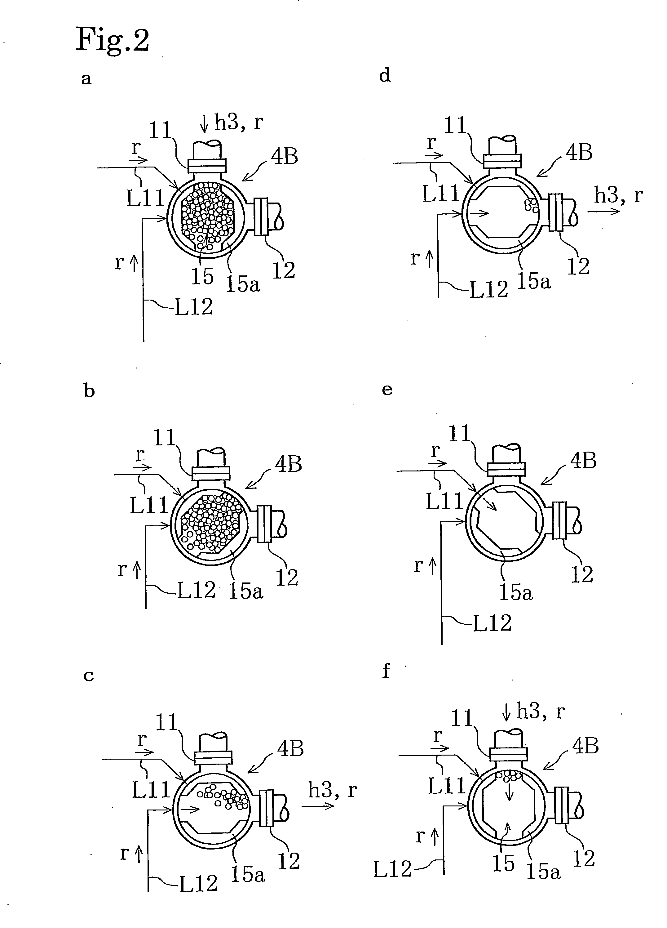
[0021]1) In the cooling / depressurizing step of cooling a gas hydrate mass (pellet) and depressurizing the pellet to a downstream-side pressure, the receiving chamber which accommodates the pellet is provided, and the pellet is depressurized to the downstream-side pressure while passing through the receiving chamber. The pellet is introduced into and immersed in a liquid refrigerant packed in the receiving chamber so that the pellet is cooled by solid / liquid contacting with the liquid refrigerant. Accordingly, a cooling gas is not discharged at the time of depressurization unlike the case of the conventional technique. Thus, no power is required for compressing a cooling gas.
[0022]Moreover, unlike a conventionally-used cooling gas, the liquid refrigerant is incompressible, and accordingly does not have to be compressed from an atmospheric pressure state to a high pressure state. Thus, no compression power is required therefor. Furthermore, the liquid refrigerant has a higher specific heat and a higher heat capacity than the cooling gas. This allows cooling of the pellet without supplying a large amount of the refrigerant. Thus, the receiving chamber can be made compact, allowing the miniaturization of the apparatus.
[0023]2) A pellet is brought into solid / liquid contact with a liquid refrigerant so that the pellet is cooled. The cooled pellet and the liquid refrigerant are discharged and depressurized. The pellet is separated from the liquid refrigerant, and the pellet is cooled by evaporation heat generated when the liquid refrigerant still attached to the pellet is volatilized. Accordingly, no power is required for compressing a cooling gas. Moreover, the pellet is cooled by the evaporation heat of the liquid refrigerant. Accordingly, the temperature of the liquid refrigerant packed in the receiving chamber does not have to be an extremely low temperature. Thus, the power for cooling the liquid refrigerant is reduced.

Problems solved by technology

However, the aforementioned LNG has an extremely low boiling point of −162° C., and has a characteristic that the LNG rapidly evaporates as the temperature rises.
Accordingly, there is a problem that, when NGH is filled into a storage container, transportation container, or the like, the filled amount is small.
Accordingly, there is a problem that the decomposition stability is slightly lowered.
Furthermore, a powder snow-like NGH is a fine particle, and accordingly has a problem of a poor handling property in carrying, storing, and unloading, for example.

Method used


Image

  • Process and appratus for producing gas hydrate
  • Process and appratus for producing gas hydrate
  • Process and appratus for producing gas hydrate

Examples


Embodiment Construction

[0091]Hereinafter, an apparatus for producing a gas hydrate according to the present invention will be described with an illustration thereof.

[0092]As shown in FIG. 1, the apparatus for producing a gas hydrate according to the present invention includes: a generating device 1 for generating a gas hydrate h by subjecting a raw-material gas g1 and raw-material water w1 to a hydration reaction; a dewatering device 2 for discharging water from a gas hydrate slurry h1 containing the gas hydrate h generated by the generating device 1; and a molding device 3 for forming pellets h3 by compressing a gas hydrate h2 dewatered by the dewatering device 2.

[0093]The generating device 1 includes: a pressure-tight container 1A connected to a supply pipe L1 for the raw-material gas g1 and to a supply pipe L2 for the raw-material water w1; and a stirring blade 1B for stirring an aqueous solution in the container 1A. A bottom portion of the pressure-tight container 1A is provided with a sparger 10 for ...


PUM


Abstract

A process is provided which includes: bringing a natural gas, e.g., methane gas or propane gas, or a mixture of these gases into gas-liquid contact with raw-material water to form a gas hydrate; compression-molding the gas hydrate into pellets; and cooling / depressurizing the pellets. Also provided is an apparatus for use in the process. In the cooling / depressurizing step 4, molded gas hydrate masses h3 in a pressurized state are cooled and depressurized to a downstream-side pressure. In the cooling / depressurizing step 4, a receiving chamber 15 which accommodates the gas hydrate masses h3 obtained in the molding step 3 is provided, and the masses h3 are depressurized to the downstream-side pressure while passing through the receiving chamber 15. The masses h3 are introduced into and immersed in a liquid refrigerant r packed in the receiving chamber 15 so that the masses h3 are cooled by solid / liquid contacting with the liquid refrigerant r.

Description

TECHNICAL FIELD[0001]The present invention relates to a process including: bringing a natural gas, e.g., methane gas or propane gas, or a mixture of these gases into gas-liquid contact with raw-material water to form a gas hydrate; compression-molding the gas hydrate into pellets; and cooling / depressurizing the pellets. The present invention also relates to an apparatus for use in the process.BACKGROUND ART[0002]Among fuel gases, particularly, natural gas (a gas mixture mainly composed of methane gas, propane gas, or the like), when in the form of liquefied natural gas, has a volume reduced down to 1 / 600th of that in its gaseous state. Accordingly, natural gas is transported in the form of liquefied natural gas (hereinafter, LNG) from a production area to a consumption area or other areas. For the transportation, an LNG carrier is used which is equipped with a tank covered and surrounded by a heat-insulating material.[0003]However, the aforementioned LNG has an extremely low boiling...

Claims


Application Information

Patent Timeline
Patent Type & Authority Applications(United States)
IPC IPC(8): F25J1/02
CPCC09K5/042F17C11/007C10L3/108C10L3/10
Inventor MURAYAMA, TETSUROUCHIDA, KAZUO
Owner MITSUI ENG & SHIPBUILD CO LTD
Learn More