
Electrically-Powered Combination Lawn Mower, Trimmer and Edger

a lawn mower and electric motor technology, applied in the field of electric motor combination lawn mowers, trimmers and edgers, can solve the problems of difficult control, time-consuming lawn maintenance, and three separate devices, and achieve the effects of convenient and fast pushing, convenient trimming, and convenient uphill pushing

Active Publication Date: 2010-12-30
LEONARDI MFG
View PDF49 Cites 18 Cited by
  • Summary
  • Abstract
  • Description
  • Claims
  • Application Information

AI Technical Summary

Benefits of technology

[0013]It is an object of this invention to provide a mowing, trimmer and edging apparatus. In one position the cutting head is positioned horizontally and can be used for mowing large areas at an even cutting height. Since there are no front wheels to get in the way of the cutting head, the cutting head can be positioned next to fences and buildings, allowing effective trimming operations with none of the disadvantages of traditional line trimmers. Also, since there is a rear caster positioned beneath the heavy battery power supply, the push point is between the two main wheels and the caster, thus preventing the trimmer from wanting to tip, which allows faster pushing and easier pushing uphill. The caster also keeps the main forward deck at a set height, facilitating even cutting during large swath lawn mowing.
[0028]According to a further aspect of the present invention, a lawn maintenance machine includes: a frame; a cutting head sub-assembly; and a motor. The cutting head assembly includes a cutting head member, a first cutting implement member and a first torsional bias member. The cutting head member defines a central axis and a first angular direction about its central axis. The cutting head member is mechanically connected to the motor so that rotation of the motor will drive the cutting head member to rotate in the first angular direction. The first cutting implement is mechanically connected to the head member through the torsional bias member so that the first cutting implement can rotate, in a biased manner, with respect to the cutting head member.

Problems solved by technology

The use of three separate devices drives cost requirements and storage space requirements.
The use of three separate devices also consumes time required for comprehensive lawn maintenance as the operator switches from one device to the next for the three operations set forth above.
The three machines are also often difficult to control properly, resulting in gouging of turf.
The high required blade speed can result in damage to tree bark and to paint on fences and buildings.
Also, if gasoline powered, the heavy vibration that results from using a hand-held trimmer can cause “hand-arm vibration syndrome” if the device is used for long periods.
This mashing action can cause browning of grass tops.
Filament line trimmers are often unusable in vegetation more robust than grass.
Traditional edgers with vertical metal blades can cause damage to driveways and walkways if proper care and / or attention is not given.
While this device does reduce the fatigue associated with carrying a hand-held line trimmer, it is not suitable for mowing large swaths of lawn, and rotating the trimmer to the vertical to conduct edge trimming requires loosening of the attachment clamp, rotation of the line trimmer and retightening of the clamp, a time-consuming process.
However, this machine does not allow 90 degree rotation of the cutting head to facilitate edging, nor does it have a third wheel or other device to ensure level and even cutting height for large swath lawn mowing.
This allows for a more stable and even cutting height for lawn mowing, but suffers from the limitation that since the filament line does not extend past the four wheels it cannot be used to trim close to a fence or building.
For example, some or all of the discussed publications may not be sufficiently early in time, may not reflect subject matter developed early enough in time and / or may not be sufficiently enabling so as to amount to prior art for patent law purposes.

Method used


Image

  • Electrically-Powered Combination Lawn Mower, Trimmer and Edger
  • Electrically-Powered Combination Lawn Mower, Trimmer and Edger
  • Electrically-Powered Combination Lawn Mower, Trimmer and Edger

Examples


Embodiment Construction

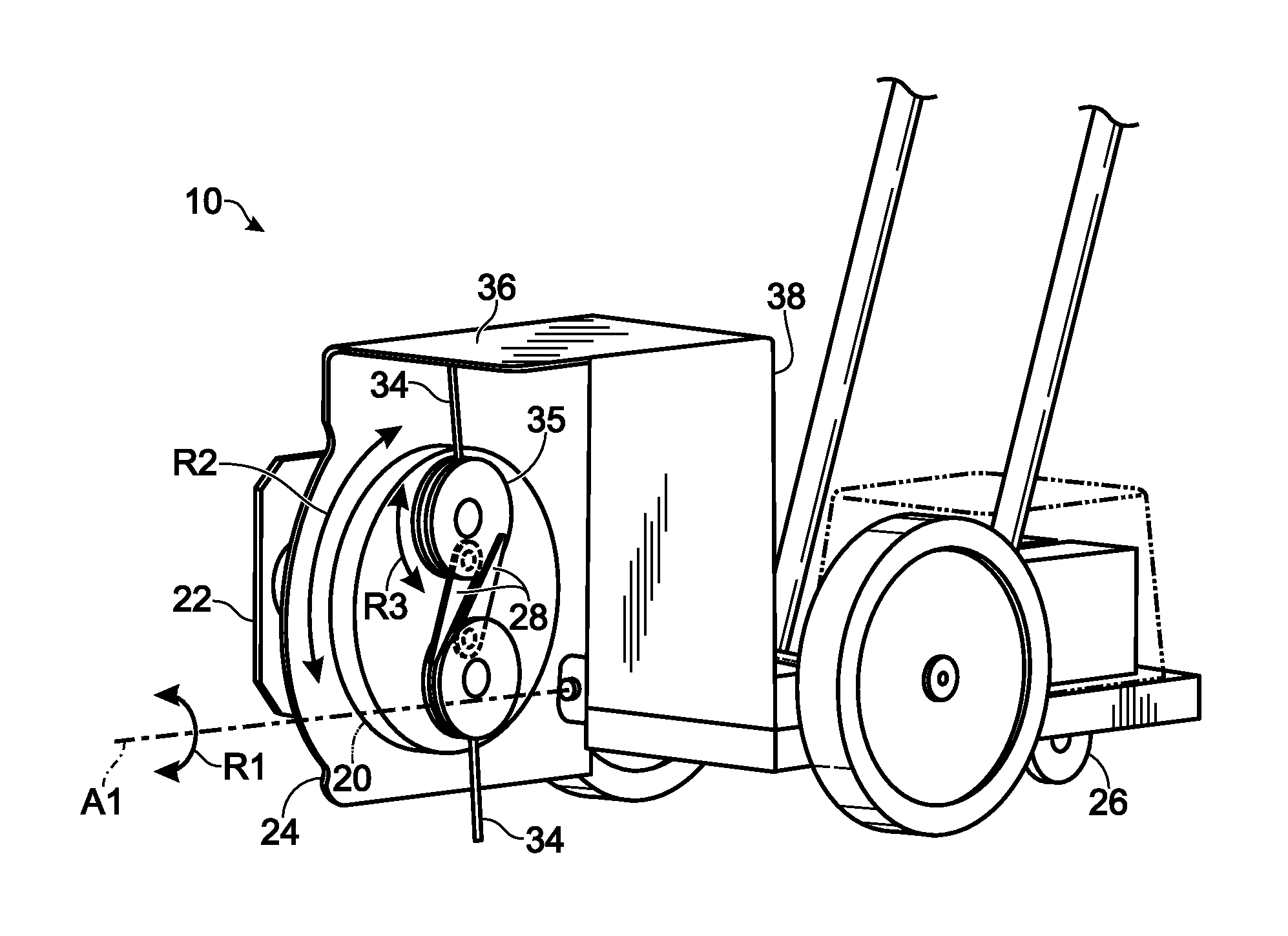
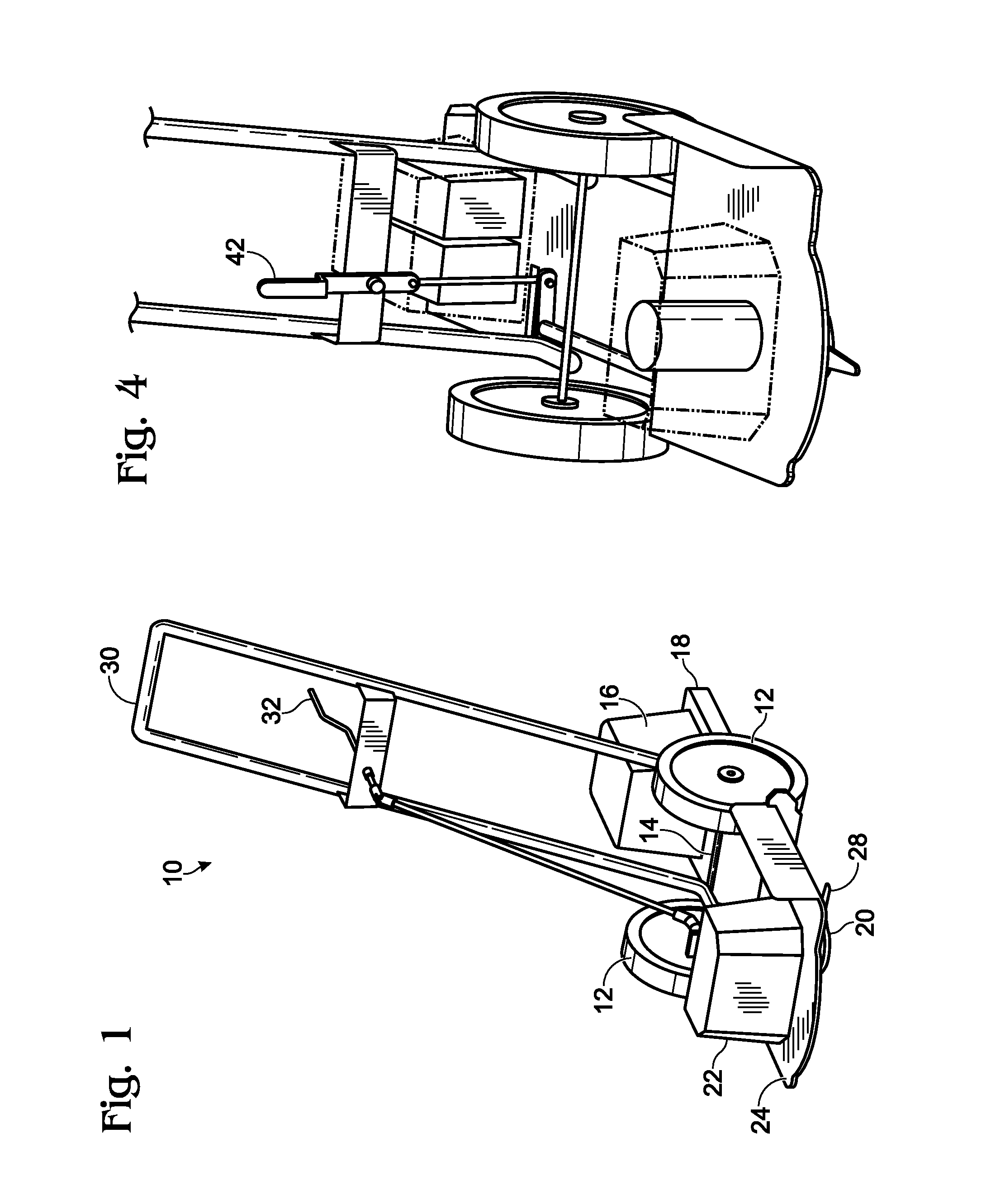
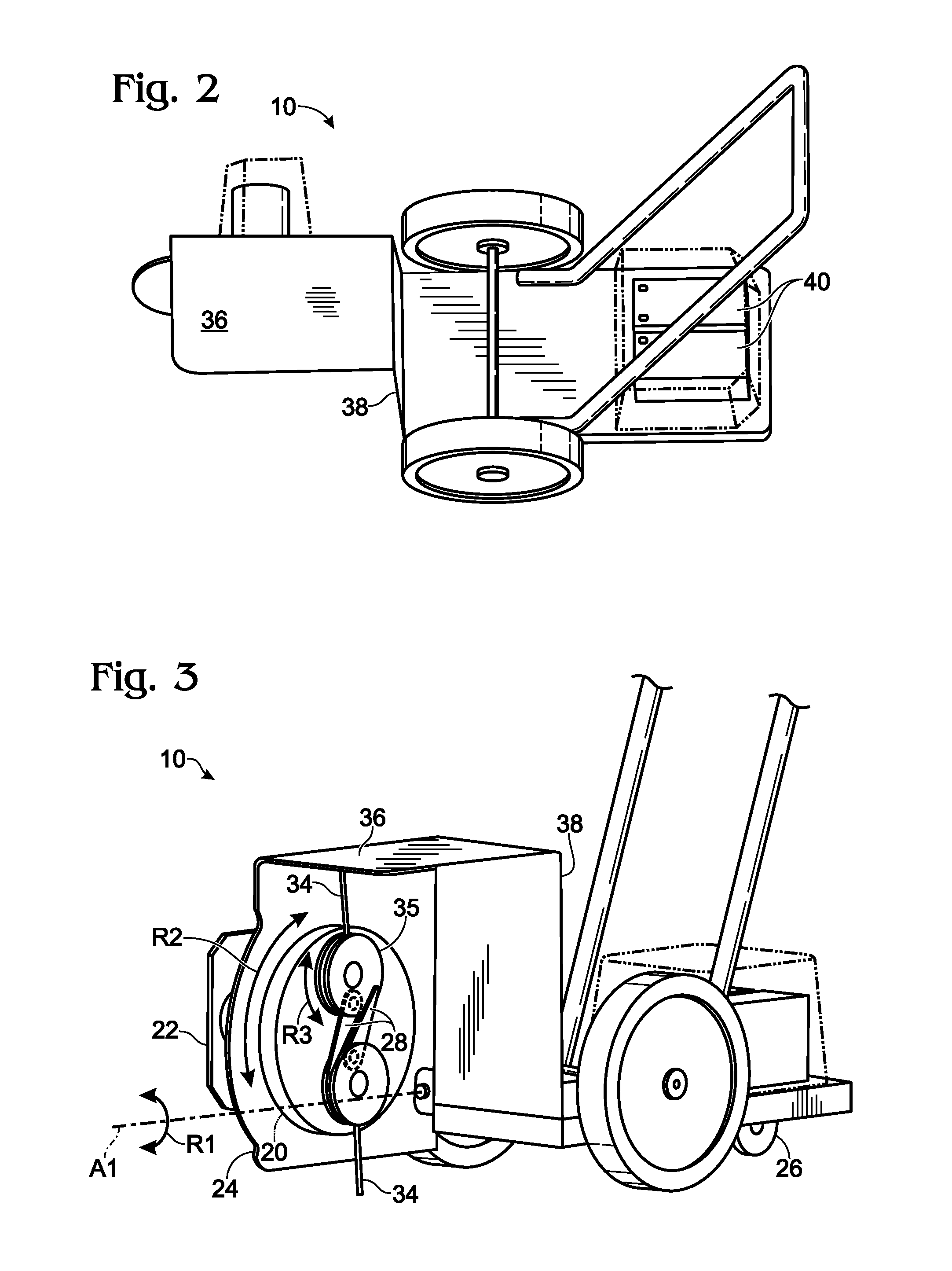
[0067]FIGS. 1-3, 21 and 22 shows the invention in a preferred embodiment 10 ready for use for mowing or trimming. The device includes a pair of main wheels 12 mounted on the opposite ends of a horizontal axle 14. The battery power supply 16 is mounted on a horizontal deck 18 behind the main wheels 12. The cutting head 20 and electric drive motor 22 are situated forward of the main wheels 12 on a forward horizontal deck 24. The electric drive motor drives the cutting head in the rotational direction R2 (see FIG. 3) in order to perform mowing, trimming and / or edging operations.

[0068]A rear caster 26 mounted under the battery power supply 16 is shown in FIG. 3. Since the battery power supply 16 is heavier than the cutting head 20 / drive motor 22 assembly, the device 10 rests on the caster 26, which provides for an even cutting height when in operation and allows faster pushing and easier pushing uphill. As seen in FIG. 1, the cutting head 20 is cantilevered out forward of the main wheel...


PUM


Abstract

An electrically powered two wheel mowing, trimming and edging apparatus is disclosed. A rotating cutting head is cantilevered in front of the wheels, with a battery positioned behind the wheels to act as a counterweight to the cutting head. A caster below the battery allows easy maneuverability and permits trimming in corners. The cutting head contains both metal cutting blades and filament line, and the operator selects which cutting tool he wants based on the type of foliage to be cut. The cutting head easily rotates from the horizontal to the vertical, allowing the apparatus to be used as an edge trimmer.

Description

RELATED APPLICATION[0001]The present application claims priority to U.S. provisional patent application No. 61 / 220,799, filed on 26 Jun. 2009; all of the foregoing patent-related document(s) are hereby incorporated by reference herein in their respective entirety(ies).BACKGROUND OF THE INVENTION[0002]1. Field of Invention[0003]The present invention relates generally to lawn maintenance devices, and, more particularly, to lawn maintenance devices that can perform more than one task such as mowing, trimming and edging and can be easily changed from one mode of operation to another.[0004]2. Description of Prior Art[0005]In lawn maintenance, the three conventional operations are: (i) general lawn cutting; (ii) trimming areas near fences, buildings and the like; and (iii) edging to make a sharp edge along a walkway, driveway or the like. These three operations are conventionally, respectively performed on three different machines. For general lawn cutting, a gasoline powered push or ridi...

Claims


Application Information

Patent Timeline
IPC IPC(8): A01D34/13
CPCA01D34/416A01D34/68A01D43/16A01D42/00A01D34/84
Inventor LEONARDI, JOSEPH A.JORDAN, BRUCE C.
Owner LEONARDI MFG
Learn More