
Air conditioning system for aircraft cabins

a technology for air conditioning systems and aircraft, which is applied in vehicle heating/cooling devices, transportation and packaging, and energy-saving board measures, etc. it can solve the problems of inevitably occurring energy losses in the process, the bleed air taken from the engine core has a particularly negative effect on the fuel consumption of the aircraft, and the relative high bypass ratio, etc., to achieve a high level of humidity

Inactive Publication Date: 2010-12-23
AIRBUS OPERATIONS GMBH
View PDF11 Cites 51 Cited by
  • Summary
  • Abstract
  • Description
  • Claims
  • Application Information

AI Technical Summary

Benefits of technology

[0002]On account of the low external temperatures and the low external pressure at high altitudes, air conditioning systems are an indispensable component of modern commercial aircraft. Only through the employment of systems of this kind is it possible to transport passengers with commercial aircraft over long distances while saving fuel.
[0037]It is advantageous if the compressed air cooling system is provided with a heat exchanger connected to the at least one air inlet of the cabin. Preferably, an air stream may be guided from the cooling device to the heat exchanger. Thus, the heat exchanger of the compressed air cooling system and the cooling device may be used in combination. The heat exchanger of the compressed air cooling system may be provided with ram air to cool an airstream to be guided to the cabin. Thereby, in particular during flights at high altitudes, cold ram air from the ambient atmosphere of the aircraft may be used efficiently.

Problems solved by technology

Modern aircraft engines have a tendency to relatively high bypass ratios, BPR, of the air streams in the engine, whereby bleed air taken from the engine core has a particularly negative effect on the fuel consumption of the aircraft.
Energy losses inevitably occur in the process, as thermal energy of the bleed air is lost through cooling.

Method used


Image

  • Air conditioning system for aircraft cabins
  • Air conditioning system for aircraft cabins
  • Air conditioning system for aircraft cabins

Examples


Embodiment Construction

[0041]In the following figures conducts for air streams are represented by solid lines without the lines having been provided with their own reference numbers in order to maintain the clarity of the figures. Lines for electric current have not been represented, likewise for reasons of clarity. It is directly obvious to the person skilled in the art from the drawings and the associated description where lines for electrical power supply and electrical signals are to be disposed. Moreover, as regards the mixing devices or mixers mentioned in this description, these are adapted to merge a plurality of air streams, in particular those which have different thermal and dynamic states. Of course a mixer can also serve as a branching and distributing device for one or a plurality of air stream(s), depending on the flow conditions. It also should be noted that most of the components described here are provided in an aircraft at least in duplicate to provide redundancy. Also, in an aircraft t...


PUM


Abstract

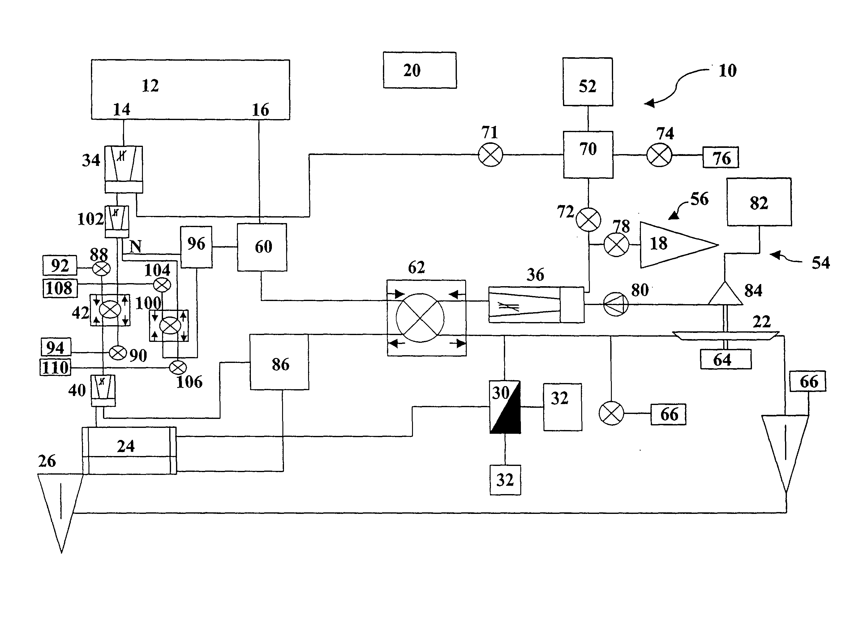
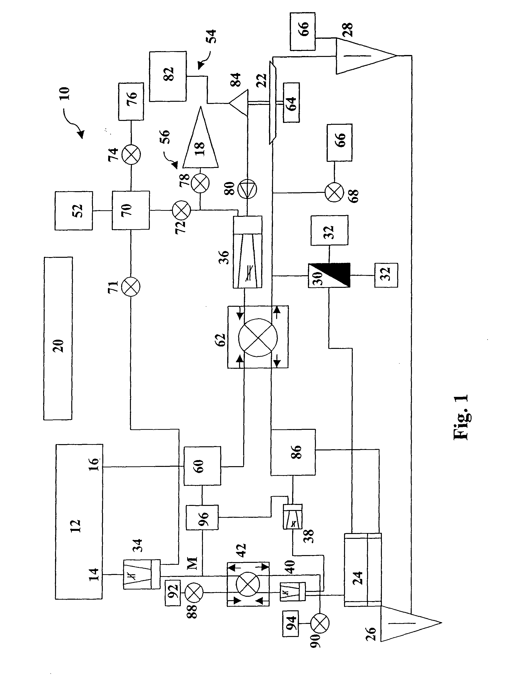
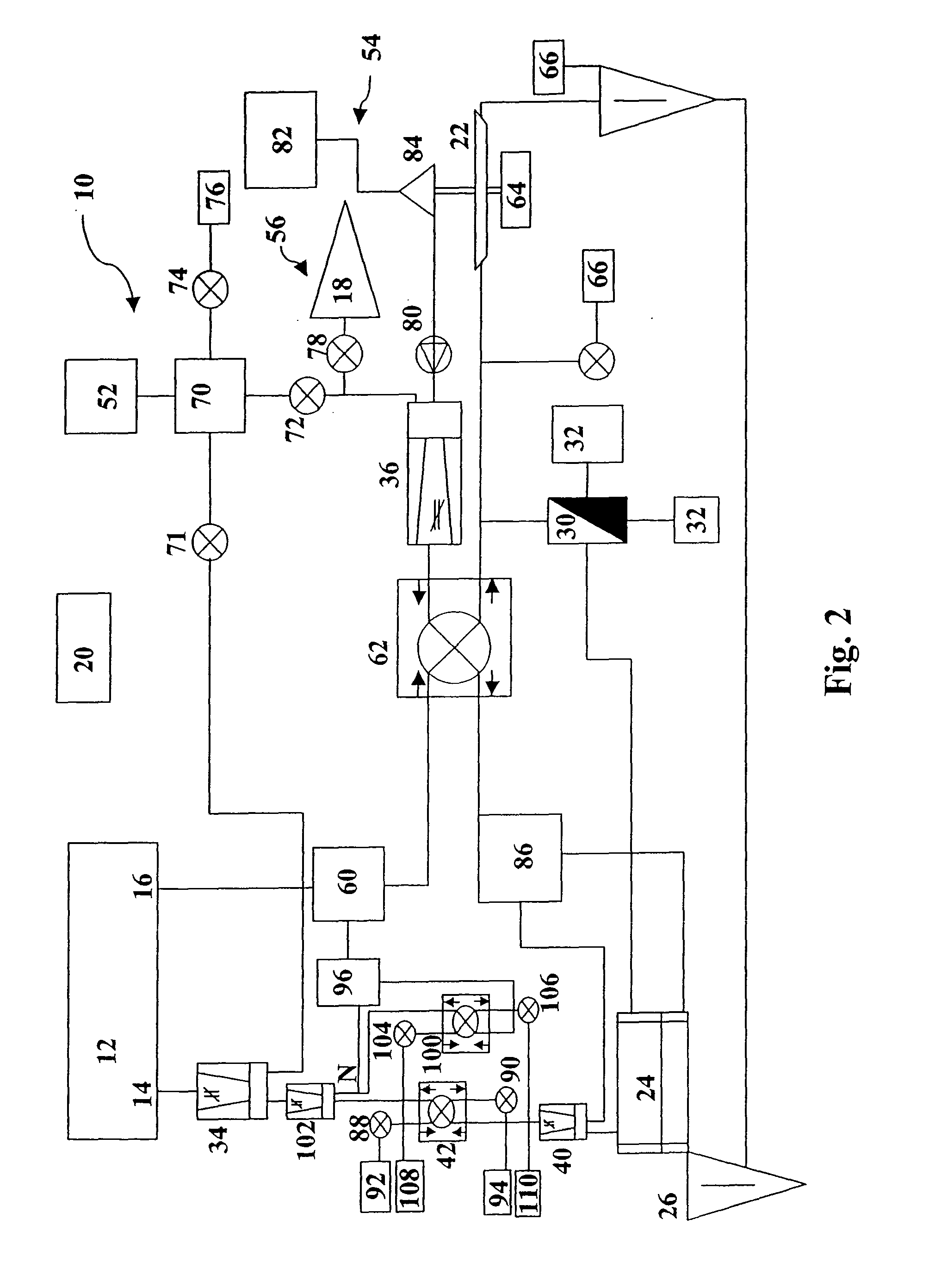
The present invention relates to an air conditioning system (10) for an aircraft cabin (12) with at least one air inlet (14) for supplying air to the cabin (12), at least one air outlet (16) for discharging air from the cabin (12) and at least one compressed-air source (52, 54, 56), which is adapted to provide pressurised fresh air for supplying to the cabin (12) via the at least one air inlet (14). The air conditioning system (10) further comprises a heat exchanger (42) supplied with ram air from a ram air inlet (92) for cooling air from the compressed-air source (52, 54, 56), wherein the heat exchanger (42) is disposed upstream of the air inlet (14) of the cabin (12). It is intended that the air conditioning system (10) comprises a cabin air heat exchanger (100) which is designed to be supplied with air discharged from the cabin (12), wherein the cabin air heat exchanger (100) is disposed downstream of the at least one air outlet (16) and upstream of a point (N) at which fresh air is mixed with air from the cabin (12).

Description

[0001]The present invention relates to an air conditioning system for an aircraft cabin with at least one air inlet for supplying air to the cabin and at least one air outlet for discharging cabin air.[0002]On account of the low external temperatures and the low external pressure at high altitudes, air conditioning systems are an indispensable component of modern commercial aircraft. Only through the employment of systems of this kind is it possible to transport passengers with commercial aircraft over long distances while saving fuel.[0003]In most cases air conditioning systems are nowadays supplied during flight with bleed air taken from the hot air stream of engines. The bleed air is as a rule branched off at one of two different points at the engine, namely an intermediate pressure port, IP, and a high pressure port, HP, depending on the flight situation. The use of bleed air is advantageous for air conditioning, as air which is under high pressure and very hot (as a rule at app...

Claims


Application Information

Patent Timeline
IPC IPC(8): B64D13/02B60H1/22
CPCB64D13/06B64D2013/0611B64D2013/0618Y02T50/56B64D2013/0662B64D2013/0688Y02T50/44B64D2013/0648Y02T50/40Y02T50/50
Inventor CREMERS, JOERGDERLIEN, HENRIKKRICKE, KLAUS-DIETERWILKE, KATJA_MARIA
Owner AIRBUS OPERATIONS GMBH
Learn More