Audio processing circuit and preamplifier circuit

a preamplifier and audio processing circuit technology, applied in the direction of low-noise amplifiers, amplifiers with tubes, low-frequency amplifiers, etc., can solve the problems of affecting the signal quality of differential outputs, linear dependence of sound pressure, and conventional preamplifiers proving inadequa

Active Publication Date: 2010-12-23
FORTEMEDIA
View PDF4 Cites 11 Cited by
  • Summary
  • Abstract
  • Description
  • Claims
  • Application Information

AI Technical Summary

Benefits of technology

[0008]In the preamplifier, a first resistor is coupled between the drain of the first transistor and the voltage ground, and a second resistor is coupled between the drain of the second transistor and the voltage ground. The reference voltage may be 0.3 volt. The first transistor and the second transistor may be P-type Metal-Oxide-Semiconductor field effect transistors (P-MOSFETs) of identical parameters.

Problems solved by technology

To maintain sensibility of the microphone, it is important not to load the microphone capacitance with a resistive load, because a resistive load will discharge the capacitor and thereby ruin the linear dependency of the sound pressure.
Thermal noise and flicker noise are unavoidably generated from those components, affecting the signal quality of the differential outputs.
The conventional preamplifier turns out to be inadequate because it consumes significant power to suppress the undesirable noises.

Method used


Image

  • Audio processing circuit and preamplifier circuit
  • Audio processing circuit and preamplifier circuit
  • Audio processing circuit and preamplifier circuit

Examples


Embodiment Construction

[0016]The following description is of the best-contemplated mode of carrying out the invention. This description is made for the purpose of illustrating the general principles of the invention and should not be taken in a limiting sense. The scope of the invention is best determined by reference to the appended claims.

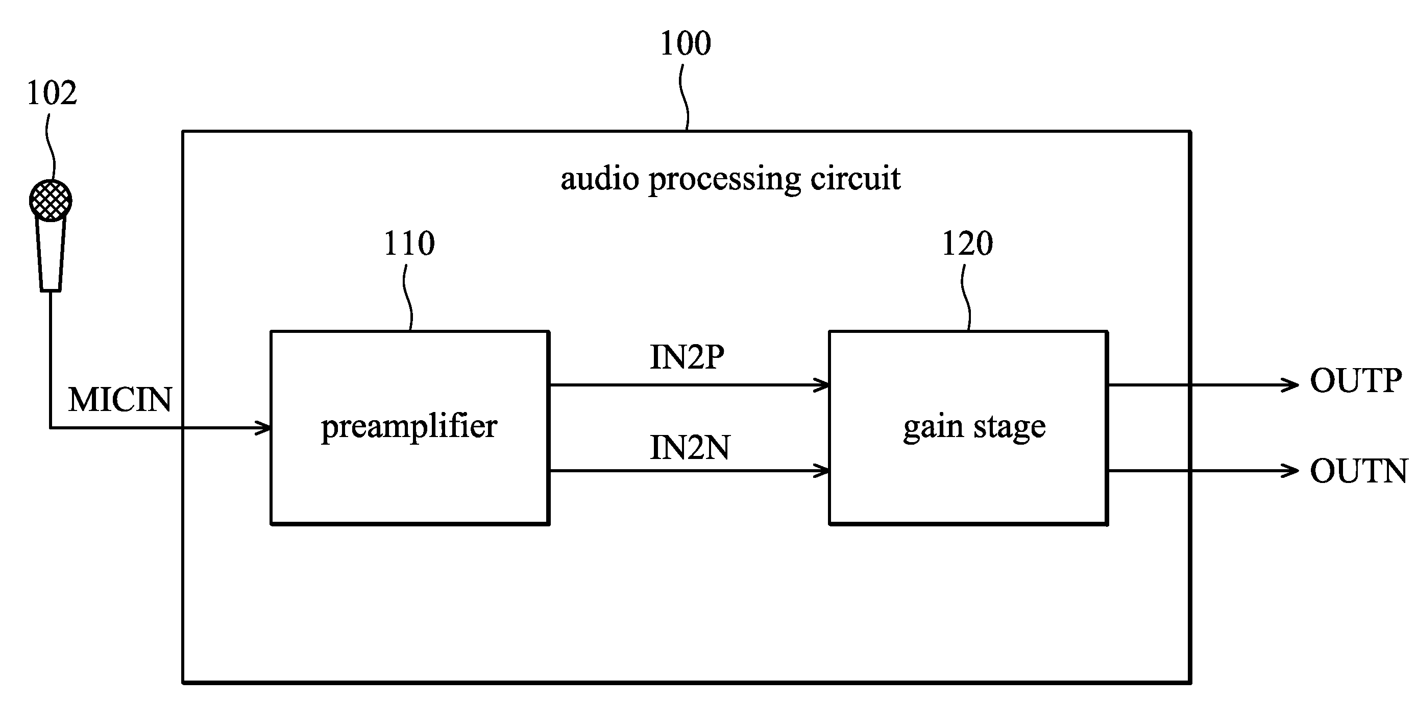
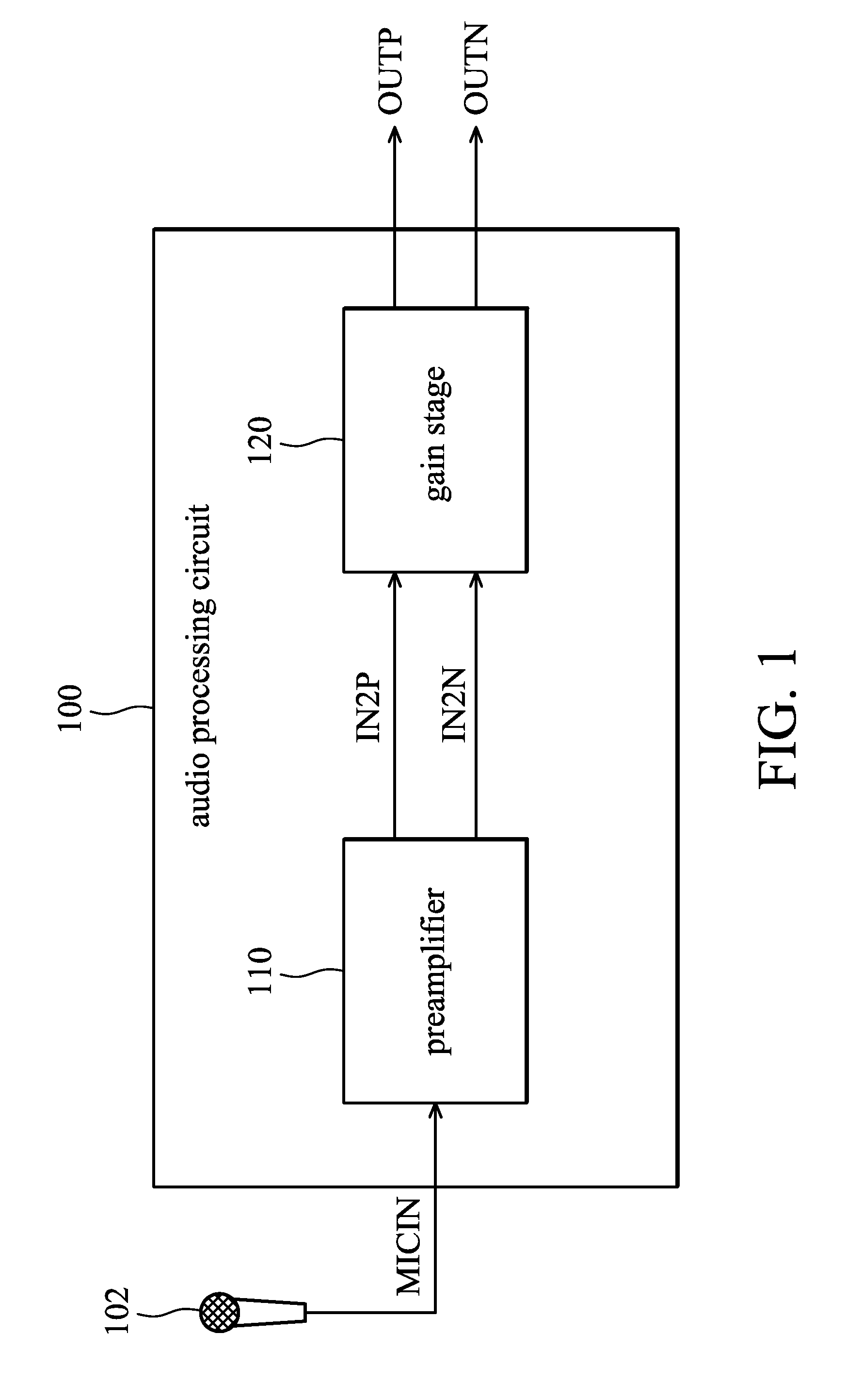
[0017]FIG. 1 shows an embodiment of an audio processing circuit 100 for processing microphone signals. The audio processing circuit 100 is preferably implemented in a chip (not shown) that may further comprise essential components such as a low pass filter (LPF), an analog to digital converter (ADC) and a digital signal processor. A microphone signal MICIN is sent from a microphone 102 to the audio processing circuit 100, and through a preamplifier 110 and a gain stage 120 in the audio processing circuit 100, a differential signal comprising a first differential output OUTN and a second differential output OUTP is output therefrom.

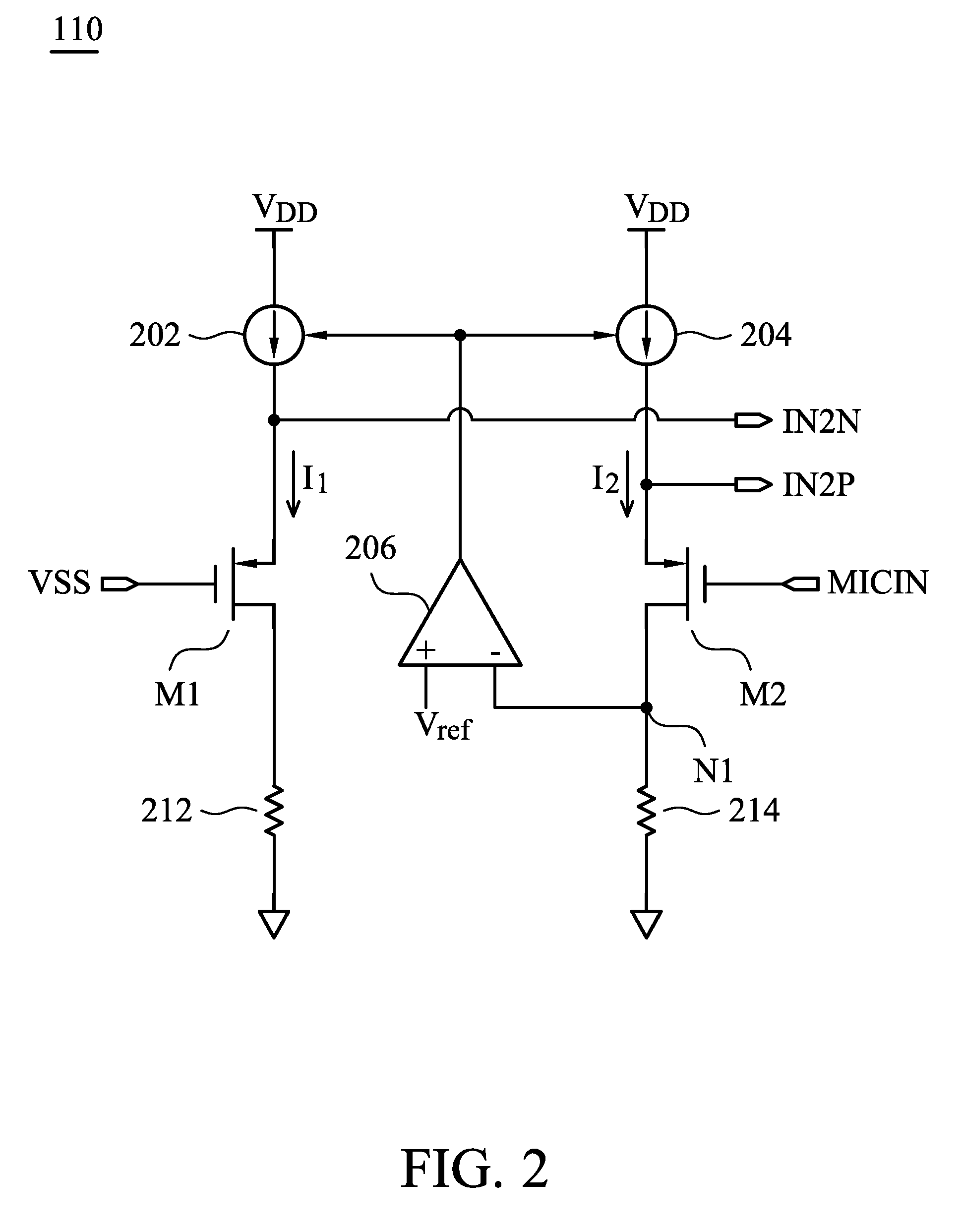
[0018]FIG. 2 shows an embodiment of th...


PUM


Abstract

An audio processing circuit is provided, receiving a microphone signal from a microphone to output a differential signal. A preamplifier receives the microphone signal to output a first preamplified voltage and a second preamplified voltage. A gain stage receives the first preamplified voltage and the second preamplified voltage to output the differential signal comprising a first differential output and a second differential output. In the preamplifier, a first operational amplifier is provided. A first voltage controlled current source is controlled by the output end of the first operational amplifier to provide a first current. A first transistor has a gate coupled to a ground voltage supply, a source coupled to the first voltage controlled current source for receiving the first current, and a drain coupled to a voltage ground. Likewise, a second voltage controlled current source and a second transistor are presented symmetrically to render the differential output.

Description

BACKGROUND OF THE INVENTION[0001]1. Field of the Invention[0002]The invention relates to a microphone preamplifier, and in particular, to a low noise design that reduces interferences caused by thermal noise and flicker noise.[0003]2. Description of the Related Art[0004]A typical microphone has a capacitor for sensing the sound pressure. As the capacitance of the capacitor varies in proportional to the sound pressure, the sound is thereby converted to a voltage signal. To maintain sensibility of the microphone, it is important not to load the microphone capacitance with a resistive load, because a resistive load will discharge the capacitor and thereby ruin the linear dependency of the sound pressure.[0005]A preamplifier is therefore required to resolve the consequences. The preamplifier is generally configured with a high input resistance, transforming the output voltage from the microphone to post stages without loss of the sensibility. The preamplifier is typically connected phys...

Claims


Application Information

Patent Timeline
Patent Type & Authority Applications(United States)
IPC IPC(8): H03F99/00H04R3/00
CPCH03F1/26H03F3/187H03F3/45475H03F2203/45544H03F2200/294H03F2200/372H03F2203/45526H03F2200/03
Inventor CHIU, JUI-TEWU, LI-TE
Owner FORTEMEDIA
Why Eureka
Try Eureka