
Optical modulator, methods of manufacturing and operating the same and optical apparatus including the optical modulator

Inactive Publication Date: 2010-12-23
SAMSUNG ELECTRONICS CO LTD +1
View PDF22 Cites 28 Cited by
  • Summary
  • Abstract
  • Description
  • Claims
  • Application Information

AI Technical Summary

Benefits of technology

[0016]One or more exemplary embodiments of the present invention include an optical modulator that has a relatively small volume and is inexpensive, may be driven with a relatively low voltage and is capable of reducing a gating time.

Problems solved by technology

However, in the binocular stereo vision method or the triangulation method, as the distance between the camera and the subject increases, accuracy of the information about the distance is rapidly reduced, and the distance measured is dependent on the surface state of the subject.
Thus it is difficult to obtain accurate information about the distance.
However, an operating voltage of the image amplifier has to be high, and the image amplifier is large sized.
Thus, gating is not completely performed in the image amplifier until light due to the charges that remain in the phosphor of the image amplifier disappears.
However, in the semiconductor-based optical modulator using the MQW, an optical gain and wavelength conversion structure is not present, and an ON / OFF ratio is low, and it is difficult to maintain the semiconductor-based optical modulator using the MQW in a completely OFF state.
However, a current loop is formed via a gate during a gating operation, and current generated in the APD is diverged by the LED and the gate so that a loss of current may occur.

Method used


Image

  • Optical modulator, methods of manufacturing and operating the same and optical apparatus including the optical modulator
  • Optical modulator, methods of manufacturing and operating the same and optical apparatus including the optical modulator
  • Optical modulator, methods of manufacturing and operating the same and optical apparatus including the optical modulator

Examples


Embodiment Construction

[0082]Reference will now be made in detail to exemplary embodiments, examples of which are illustrated in the accompanying drawings, wherein like reference numerals refer to the like elements throughout. In this regard, the present exemplary embodiments may have different forms and should not be construed as being limited to the descriptions set forth herein. Accordingly, the exemplary embodiments are merely described below, by referring to the figures, to explain aspects of the present description.

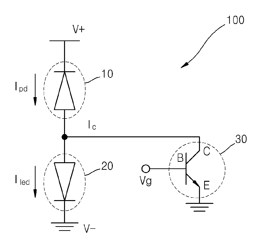
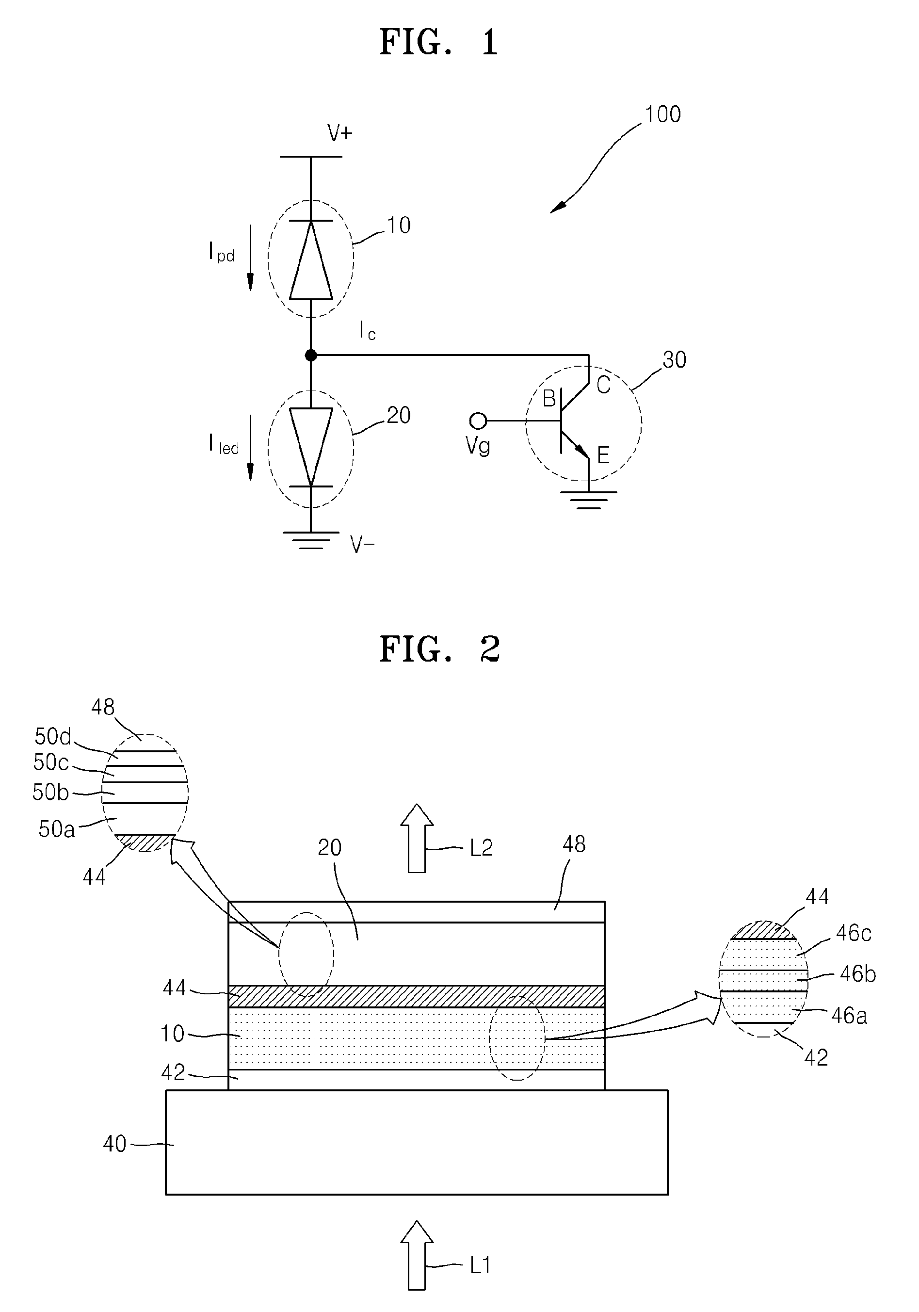
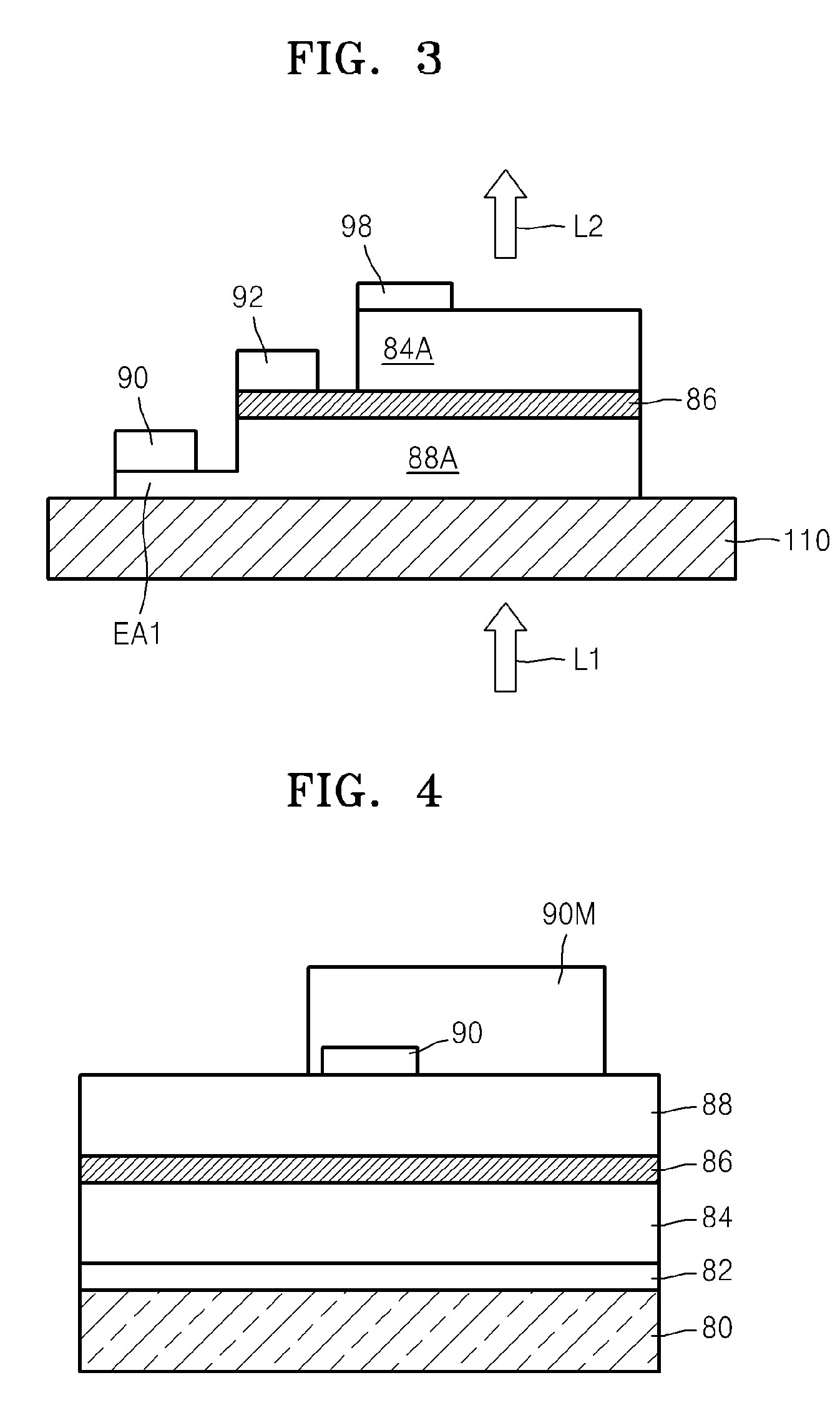
[0083]FIG. 1 is a circuit diagram of a first optical modulator 100 according to an exemplary embodiment of the present invention. Referring to FIG. 1, the first optical modulator 100 according to the present exemplary embodiment may have an optical amplification function and a wavelength conversion function as well as an optical shutter function. Thus, when light that is incident on the first optical modulator 100 is near infrared light, light to be output from the first optical modulator...


PUM


Abstract

An optical modulator, methods of manufacturing and operating the same, and an optical apparatus including the optical modulator are disclosed. The optical modulator includes an electro-optical converter and an optical-electric converter, stacked perpendicular to a substrate, and a gate transistor. The gate transistor gates a signal transmitted to the electro-optical converter from the optical-electric converter and allows charges generated in the optical-electric converter and charges remaining in the electro-optical converter to flow while bypassing the electro-optical converter when gating ON is performed.

Description

CROSS-REFERENCE TO RELATED APPLICATIONS[0001]This application claims the benefit of Korean Patent Application No. 10-2009-0053996, filed on Jun. 17, 2009, in the Korean Intellectual Property Office, and the disclosure of which is incorporated herein in its entirety by reference.BACKGROUND[0002]1. Field[0003]One or more exemplary embodiments of the present invention relate to an optical modulator and methods of manufacturing and operating the same, and more particularly, to an optical modulator having a gating function, methods of manufacturing and operating the same, and an optical apparatus including the optical modulator.[0004]2. Description of the Related Art[0005]An additional unit is used in order to obtain information about the distance between a camera that takes two-dimensional images and a subject. The information about the distance between the camera and the subject may be obtained by using a binocular stereo vision method using two cameras or a triangulation method using ...

Claims


Application Information

Patent Timeline
IPC IPC(8): G02F1/03H01L31/18
CPCG01S7/4816G01S17/89G02F1/025G02F1/01708G01S7/4914G01J1/00G01J1/44H03K17/00
Inventor CHO, YONG-CHULJANG, JAE-HYUNGPARK, YONG-HWAPARK, CHANG-SOOSONG, JONG-IN
Owner SAMSUNG ELECTRONICS CO LTD
Learn More