Method of manufacturing polarizer, polarizer, polarizing plate, optical film, method of manufacturing composite polarizing plate, composite polarizing plate and image display

a technology of polarizers and polarizing plates, which is applied in the field of manufacturing polarizers, polarizers, polarizing plates, optical films, and methods of manufacturing composite polarizing plates, which can solve the problems of inability to clean, inability to manufacture pva films, etc., so as to achieve the effect of increasing the number of processes, and reducing the number of manufacturing processes

Inactive Publication Date: 2010-12-23
NITTO DENKO CORP
View PDF6 Cites 6 Cited by
  • Summary
  • Abstract
  • Description
  • Claims
  • Application Information

AI Technical Summary

Benefits of technology

[0027]Preferably, in the manufacturing method of a polarizer of the present invention, a process, in which the contact with the liquid is carried out by spraying, is carried out while feeding the hydrophilic polymer film in a longitudinal direction. Further, it is preferable that spraying is carried out in a space in which the sprayed liquid is prevented from being leaked to an external environment by a leak preventing means. In a case where the contact with the liquid is carried out by spraying, some of the liquid mist generated by spraying is not brought into contact with the hydrophilic polymer film but dispersed by air currents. In this state, spraying in the space, in which leak of the liquid is prevented, makes it possible to greatly reduce leak of the dispersed liquid to an external environment and to easily collect the dispersed liquid. As a result, health of workers is prevented from being damaged because of the dispersed liquid and reuse and disposal of the liquid after collection can be eased. The leak of the liquid is not always required to be completely prevented. The present invention is applicable as long as the leak of the liquid is practically prevented in a range in which advantage of the present invention is not undermined. Slight leak of the liquid may be allowable. For example, the liquid may slightly leak from clearance at a position where the grip means (for example, a tenter clip, etc.) is disposed. The leak preventing means is not particularly limited as long as the leak of the liquid is practically prevented, and examples thereof include a spray booth, and the like. Preferably, the spray booth has a carrying-in entrance and a carrying-out exit of the hydrophilic polymer film.
[0028]In the manufacturing method of a polarizer of the present invention, it is preferable that the pressure in the space, in which leak of the liquid is prevented, is negative to the outside (to make the pressure in the space, in which leak of the liquid is prevented, lower than pressure of the outside). For example, by making the pressure in the spray booth being negative to that of the outside, air current from the outside to the inside of the spray booth is generated, and leak of the dispersed liquid to the outside environment from the carrying-in entrance and the carrying-out exit is efficiently prevented.
[0029]In the manufacturing method of a polarizer of the present invention, it is preferable that the hydrophilic polymer film is a polyvinyl alcohol film and the dichroic material is iodine.
[0030]A polarizer of the present invention is manufactured by the aforementioned method of manufacturing a polarizer of the present invention.
[0031]A polarizing plate of the present invention includes a protective layer laminated on at least one surface of a polarizer, wherein the polarizer is the aforementioned polarizer of the present invention.
[0032]An optical film of the present invention includes a retardation film laminated on at least one surface of a polarizer or a polarizing plate, wherein the polarizer is the aforementioned polarizer of the present invention and the polarizing plate is the aforementioned polarizing plate of the present invention.

Problems solved by technology

However, with the aforementioned method, when a PVA film is brought into contact with liquid by immersing in a bath, the bath is required.
Therefore, with the aforementioned method, a manufacturing equipment tends to be getting larger.
Further, with a tenter method, an up-and-down movement of the PVA film is structurally difficult.
Therefore, a combination of stretch by the tenter method and immersion of the PVA film into the bath, which are simultaneously performed, requires a very complicated structure.

Method used


Image

  • Method of manufacturing polarizer, polarizer, polarizing plate, optical film, method of manufacturing composite polarizing plate, composite polarizing plate  and image display
  • Method of manufacturing polarizer, polarizer, polarizing plate, optical film, method of manufacturing composite polarizing plate, composite polarizing plate  and image display
  • Method of manufacturing polarizer, polarizer, polarizing plate, optical film, method of manufacturing composite polarizing plate, composite polarizing plate  and image display

Examples


example 1

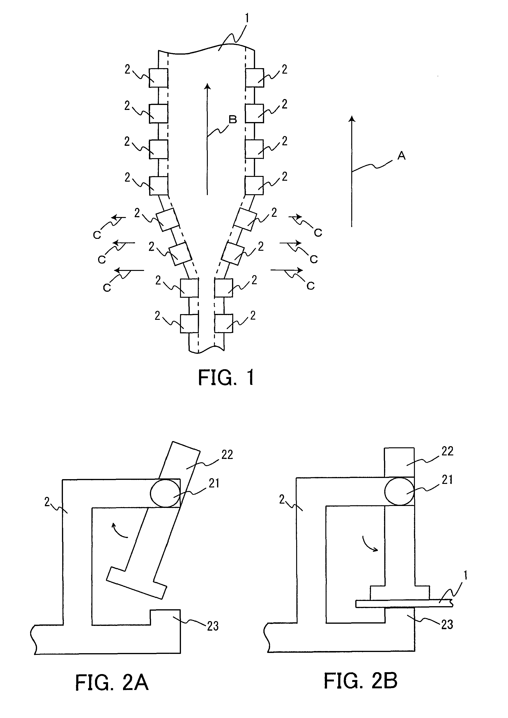
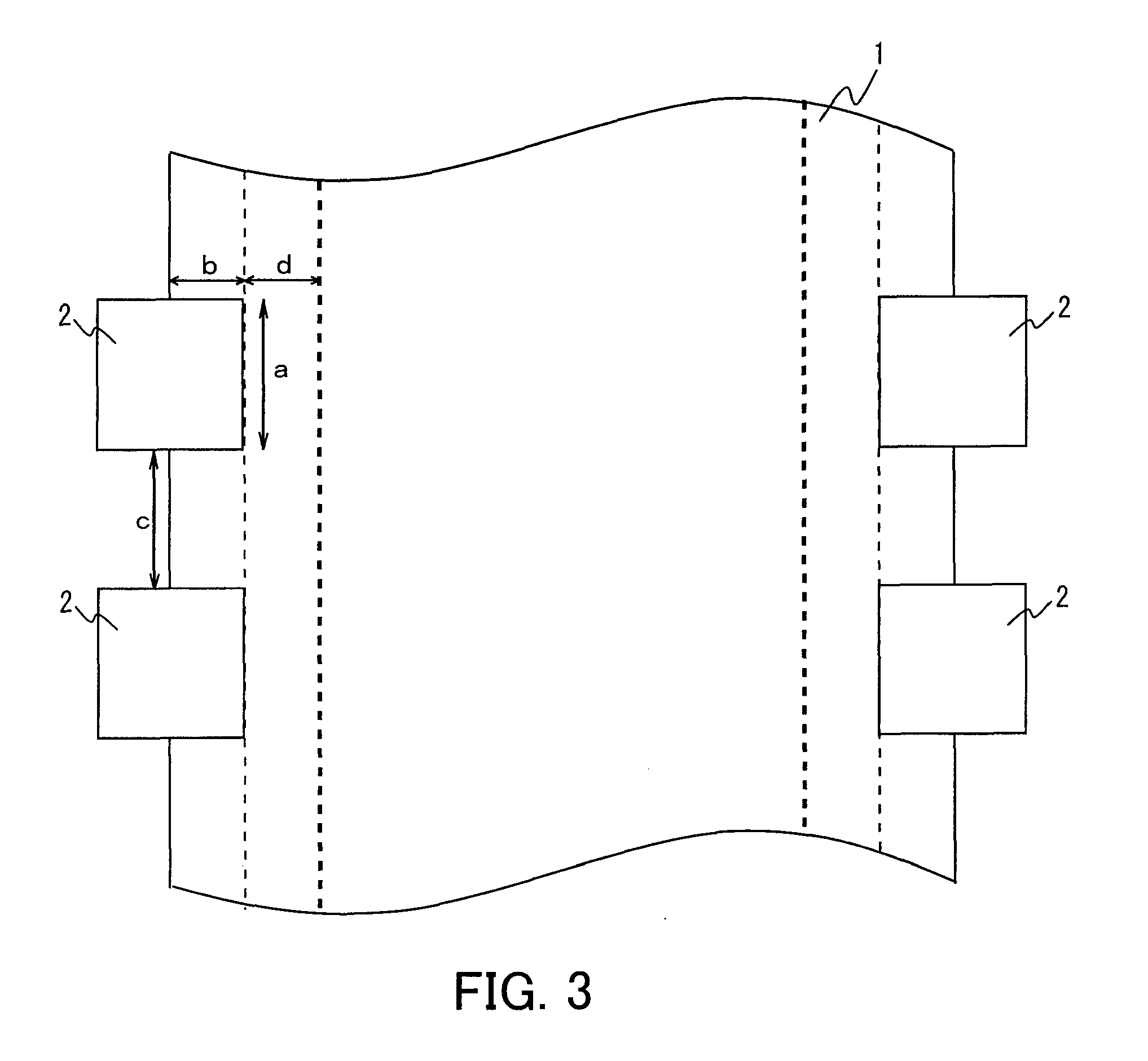
[0124]An original PVA film (“VF-PS” (trade name), manufactured by Kuraray Co., Ltd.) was prepared. This PVA film had a thickness of 75 μm. The following each process was carried out while gripping both ends of the PVA film in a width direction thereof by tenter clips (grip means) and feeding the PVA film in a longitudinal direction thereof using a tenter stretching machine. The length of a grip range by the tenter clips (grip means) was 14 mm and the width of the grip range by the tenter clips (grip means) was 19 mm. Further, the distance between the tenter clips (grip means), which are adjacent in a longitudinal direction of the PVA film, was 10 mm.

(1) Swelling Process

[0125]In the gas phase, water (a swelling liquid) of a room temperature (23° C.) was sprayed onto one surface of the PVA film for 30 seconds. In this state, a line was imaged that connects inner ends of the tenter clips (grip means) in a width direction of the PVA film, the grip means being adjacent in a longitudinal ...


PUM

PropertyMeasurementUnit
widthaaaaaaaaaa
thicknessaaaaaaaaaa
thicknessaaaaaaaaaa

Abstract

A method of manufacturing a polarizer is provided that makes it possible to virtually simultaneously perform a contact of a hydrophilic polymer film with liquid and stretch of the hydrophilic polymer film in a width direction by a tenter method, or the like, using a small and simple manufacturing equipment. A method of manufacturing a polarizer includes a width direction stretching process for stretching a hydrophilic polymer film 1 in the width direction, which is continuously supplied, by gripping both ends in a width direction thereof with grip means 2 and moving the grip means 2 in a longitudinal direction of the film 1 as well as by bringing the film 1 into contact with liquid and also moving the grip means 2, which grips at least one of both ends in the width direction of the film 1, outwardly in the width direction of the film 1; and a dyeing process for dyeing the film 1 by a dichroic material. In the width direction stretching process, a contact with the liquid is carried out by at least one of spraying and coating of the liquid, and the width direction stretching process is carried out in at least one of the dyeing process and a process other than the dyeing process.

Description

TECHNICAL FIELD [0001]The present invention relates to methods of manufacturing polarizers, polarizers, polarizing plates, optical films, methods of manufacturing composite polarizing plates, composite polarizing plates, and image displays.BACKGROUND ART [0002]Polarizers are used for various liquid crystal displays (LCDs) for television sets, personal computers, cell-phones, etc. Usually, the polarizers are manufactured by dyeing and uniaxially-stretching polyvinyl alcohol (PVA) films. When a PVA film is uniaxially-stretched, the dichroic material adsorbed by (dyeing) the PVA molecules is oriented and thereby the PVA film becomes a polarizer.[0003]Recently, the use of LCDs for television sets is increasing rapidly, and the size of the screens thereof also is increasing. Accordingly, there also are demands for an increase in size of polarizers that are used for television sets. As a method of manufacturing such large-sized polarizers, there is a proposal for a method of stretching a ...

Claims


Application Information

Patent Timeline
Patent Type & Authority Applications(United States)
IPC IPC(8): G02F1/1335G02F1/29B05D5/06B32B37/14
CPCB29C55/026B29C55/08G02B5/3083B29K2995/0034G02B5/3033B29C55/20G02B5/30G02F1/1335
Inventor HATSUDA, RYOTAUMEMOTO, SEIJIHADA, KAZUYAYOSHIMI, HIROYUKIHIRATA, SATOSHI
Owner NITTO DENKO CORP
Why Eureka
Try Eureka