Fuel injection valve and fuel injection device
a technology of fuel pressure sensor and fuel injection valve, which is applied in the direction of liquid fuel feeder, machine/engine, mechanical apparatus, etc., can solve the problems of difficulty in accurately measuring the pressure of fuel, and achieve the effect of avoiding the deterioration of the measurement accuracy of the fuel pressure sensor, facilitating the concentration of stress, and avoiding the deterioration of the measurement accuracy
- Summary
- Abstract
- Description
- Claims
- Application Information
AI Technical Summary
Benefits of technology
Problems solved by technology
Method used
Image
Examples
first embodiment
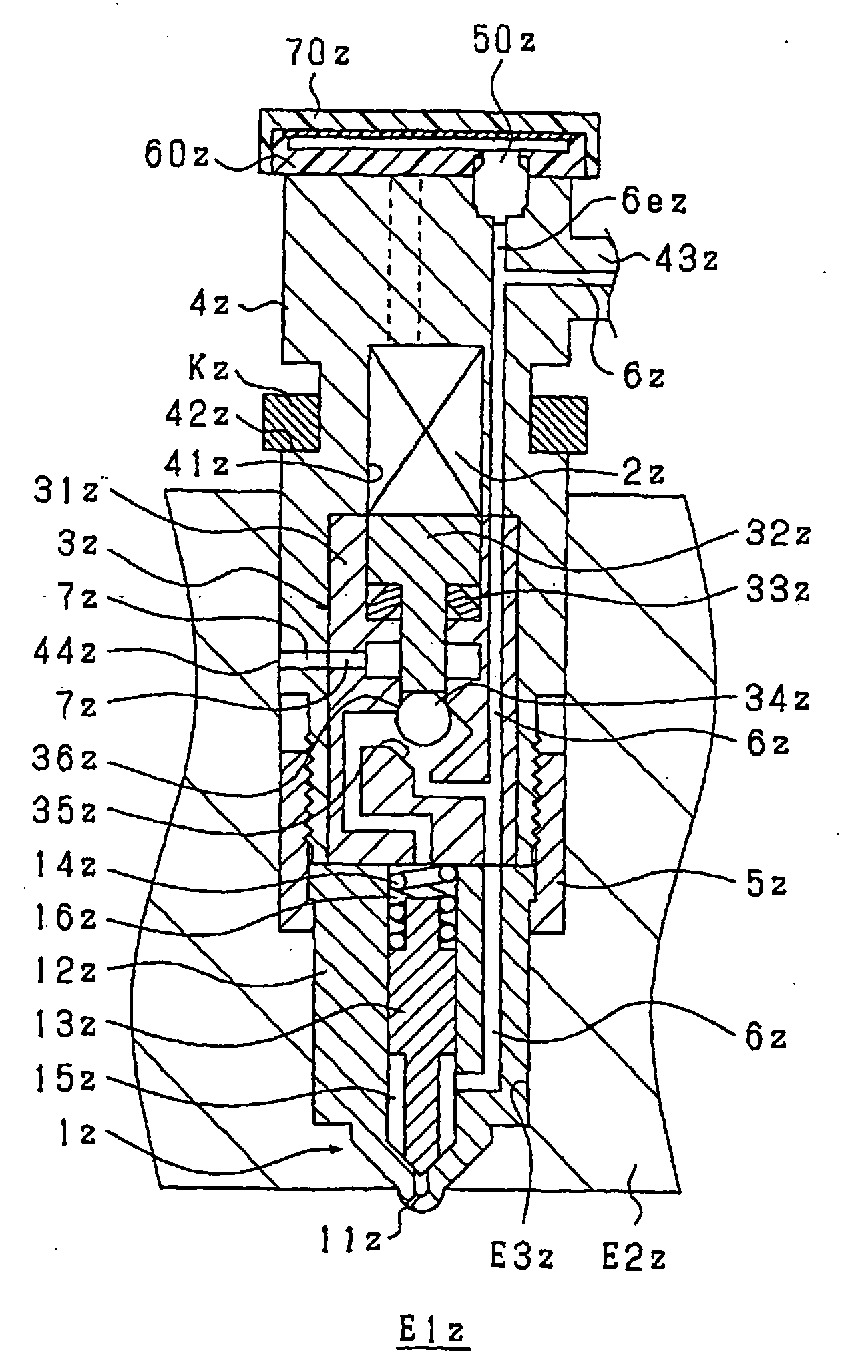
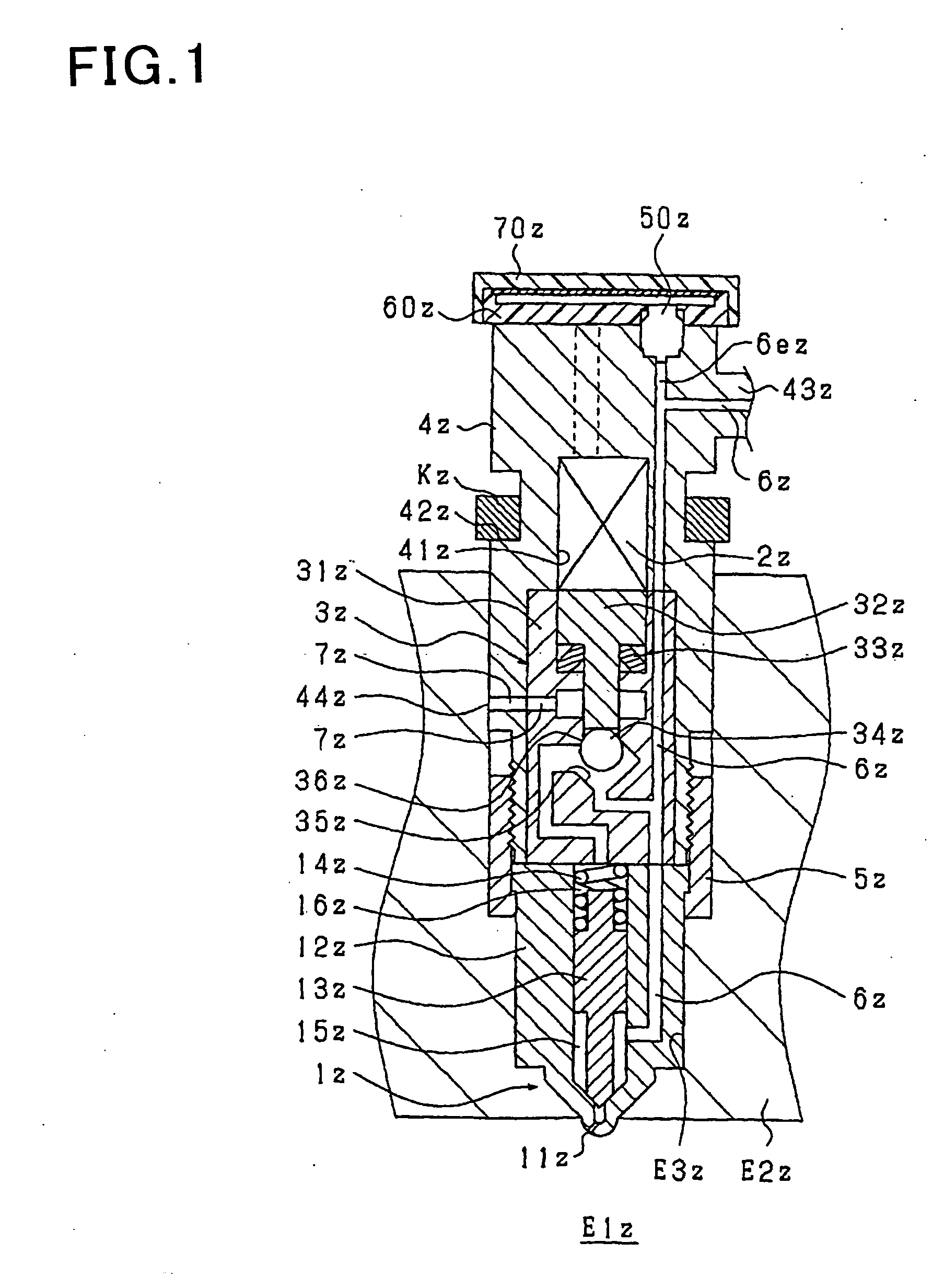
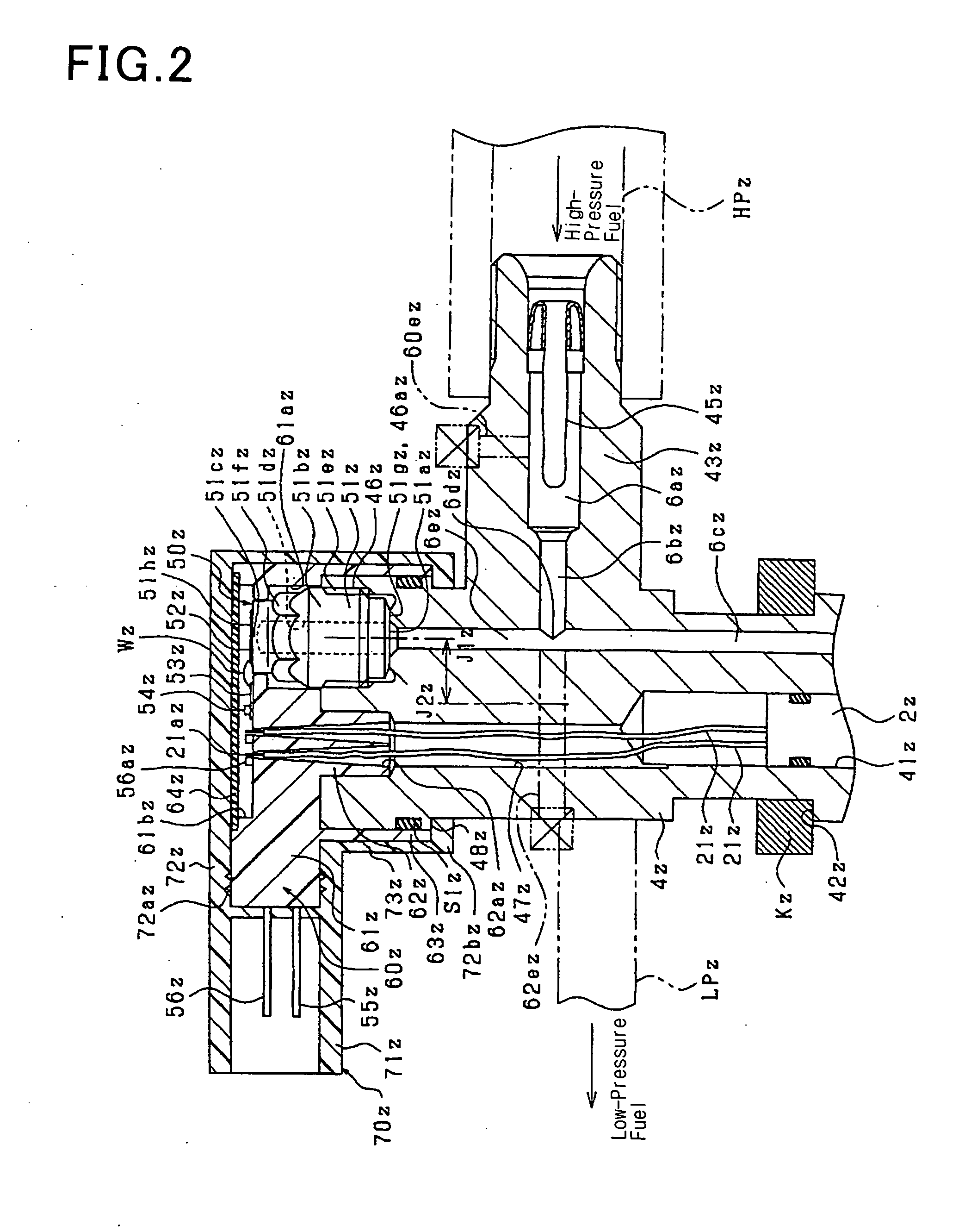
[0192]The first embodiment of the invention will be described using FIGS. 1 and 2. FIG. 1 is a schematic sectional view which shows an outline of inner structure of an injector (i.e., a fuel injection valve) according to this embodiment FIG. 2 is an enlarged view for explaining FIG. 1 in detail.
[0193]First, a basic structure and operation of the injector will be described based on FIG. 1. The injector is to spray high-pressure fuel, as stored in a common rail (not shown), into a combustion chamber E1z formed in a cylinder of an internal combustion diesel engine and includes a nozzle 1z for spraying the fuel when the valve is opened, a piezo actuator 2z (opening / closing mechanism) which expands or contracts when charged or discharged electrically, and a back pressure control mechanism 3z (opening / closing mechanism) which is driven by the piezo actuator 2z to control the back pressure acting on the nozzle 1z.
[0194]The nozzle 1z is made up of a nozzle body 12z in which spray holes 11z...
second embodiment
[0233]The first embodiment is so designed that the installation of the fuel pressure sensor 50z in the injector body 4z is achieved by fitting it into the injector body 4z from outside the axial line J2z of the cylindrical injector body 4z. In contrast to this, the embodiment of FIG. 3 is designed to achieve the installation from radially outside the cylindrical body 4z. Specifically, the cylindrical injector body 4z has formed in an outer circumferential surface a recess 461z into which the cylinder 51bz of the stem 51z of the fuel pressure sensor 50z is to be fitted. Therefore, a sealing surface 461az of the body 4z which creates the metal-to-metal touch seal between itself and the stem 51z is oriented so as to expand in parallel t the axial line J2z.
[0234]The high-pressure port 43z of the injector of the first embodiment is so oriented as to join the high-pressure pipe HPz in the radial direction of the injector. The high-pressure port 4311 of this embodiment is so oriented as t...
third embodiment
[0236]In the second embodiment, the branch path 6ez diverges from the large-diameter portion 6az of the high-pressure path 6z, but this embodiment of FIG. 4 has the branch path 6ez diverging from a small-diameter portion 6bz of the high-pressure path 6z.
[0237]The diverging of the branch path 6ez from the high-pressure paths 6az and 6bz facilitates the concentration of stress on a portion of the body 4z (i.e., a branching portion) where the high-pressure paths 6az and 6bz intersects with the branch path 6ez, thus requiring the need for ensuring the strength of the body 4z. This embodiment has the branch path 6ez diverging from the small-diameter portion 6bz, thus improving the strength of the branching portion of the body 4z as compared with when the branch path 6ez diverges from the large-diameter portion 6az.
PUM
 Abstract
Description
Claims
Application Information
 - Generate Ideas
- Intellectual Property
- Life Sciences
- Materials
- Tech Scout
- Unparalleled Data Quality
- Higher Quality Content
- 60% Fewer Hallucinations
Browse by: Latest US Patents, China's latest patents, Technical Efficacy Thesaurus, Application Domain, Technology Topic, Popular Technical Reports.
© 2025 PatSnap. All rights reserved.Legal|Privacy policy|Modern Slavery Act Transparency Statement|Sitemap|About US| Contact US: help@patsnap.com


