
Double-exposure method

a double-exposure, photoresist technology, applied in the direction of photomechanical treatment, instruments, electrical equipment, etc., can solve the problems of affecting the first photoresist pattern, not appearing to be ready in time, etc., to reduce the requirement for nonlinear photoresist, the effect of extending the lithography capability and increasing the lithography resolution

Inactive Publication Date: 2010-12-09
SHANGHAI INTEGRATED CIRCUIT RES & DEV CENT
View PDF1 Cites 25 Cited by
  • Summary
  • Abstract
  • Description
  • Claims
  • Application Information

AI Technical Summary

Benefits of technology

[0037]To sum up, by introducing RELACS polymer and process into double exposure process, the present invention of double exposure method not only realizes a higher lithography resolution and extends the lithography capability of present lithography tools, but also eliminates the influence of the second exposure on the first photoresist pattern, thus reducing the requirement for nonlinear photoresist in double-exposure technology.

Problems solved by technology

With semiconductor devices scaling down, the Critical Dimension (CD) of photolithography is beyond the limit of optical lithography, which brings great challenges to semiconductor manufacturing industry, especially to photolithography technology.
Extreme ultraviolet (EUV) lithography has higher resolution, but for some reason it does not appear to be ready in time.
However, because the second photoresist layer is directly coated on the first photoresist pattern, the second exposure will inevitably affect the first photoresist pattern.

Method used


Image

  • Double-exposure method
  • Double-exposure method
  • Double-exposure method

Examples


Embodiment Construction

[0040]Details of this present invention will be further described in combination with the preferred embodiments and the drawings to make the purposes and features of the present invention more obvious and more understandable.

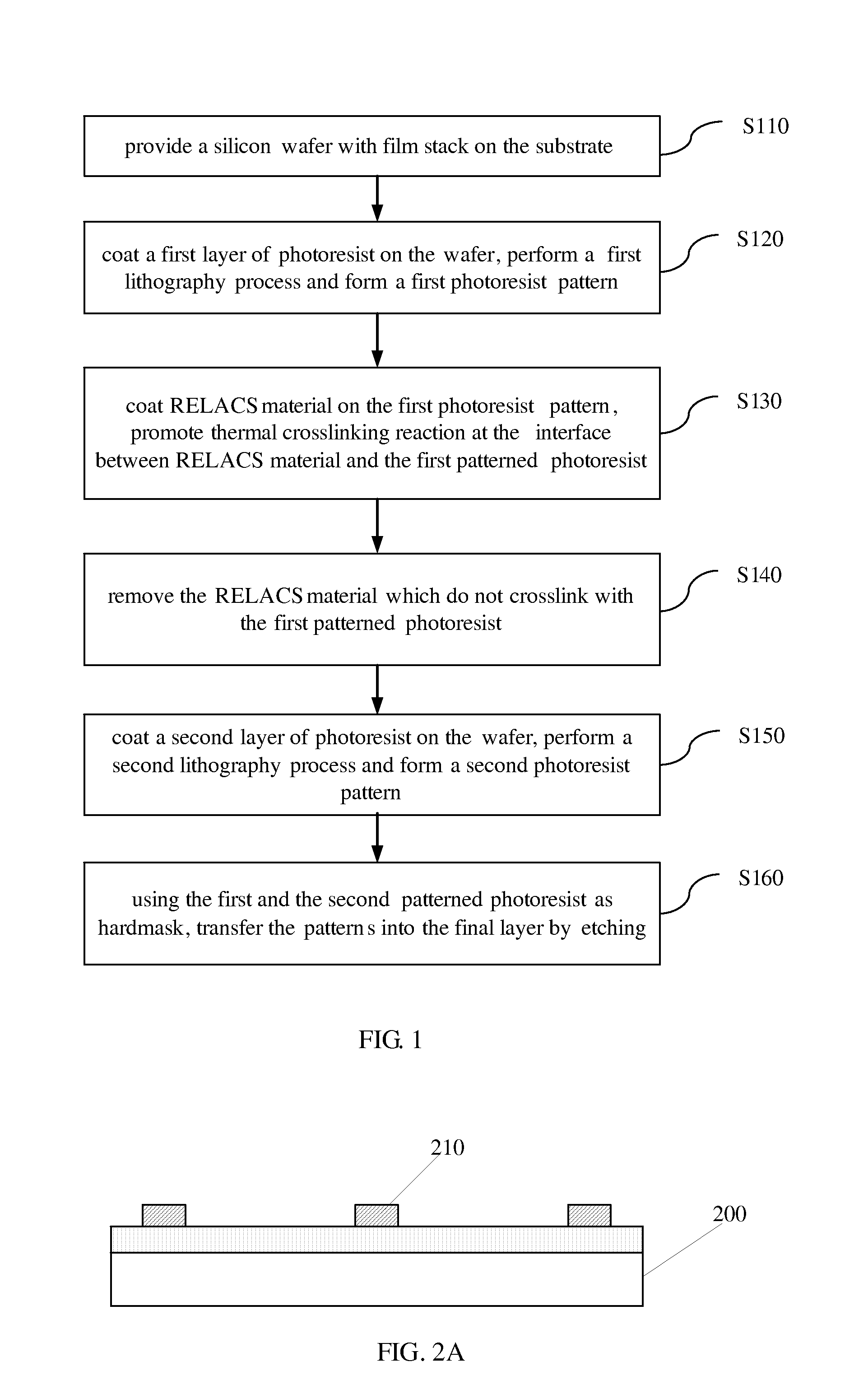
[0041]One embodiment of the present invention provides a double-exposure method. The method comprises a first lithography process and a second lithography process. Between the first and the second lithography process, the method further comprises: coat RELACS material on the first photoresist pattern, promote thermal crosslinking reaction at the interface between RELACS material and the first photoresist pattern.

[0042]Remove RELACS material which does not crosslink with the first photoresist pattern.

[0043]To describe the method of the embodiment more clearly and more specifically, refer to FIG. 1 of the flow chart of the double-exposure method provided by an embodiment of the present invention, and see FIGS. 2A-2E for reference, wherein the method comprises the ...


PUM


Abstract

The present invention discloses a double-exposure method comprising a first lithography process and a second lithography process. Between the first and the second lithography process, coat Resolution Enhancement Lithography Assisted by Chemical Shrink (RELACS) material on the first photoresist pattern, promote thermal crosslinking reaction at the interface between the RELACS materials and the first photoresist pattern; afterwards, remove the RELACS material which does not crosslink with the first photoresist pattern. This method not only realizes higher lithography resolution, but also avoids the adverse effects of the second exposure on the first photoresist pattern in double-exposure technology.

Description

BACKGROUND OF THE INVENTION[0001]1. Technical Field[0002]The present invention relates to semiconductor manufacturing field, and more especially, to a double-exposure method.[0003]2. Description of Related Art[0004]With semiconductor devices scaling down, the Critical Dimension (CD) of photolithography is beyond the limit of optical lithography, which brings great challenges to semiconductor manufacturing industry, especially to photolithography technology. Extreme ultraviolet (EUV) lithography has higher resolution, but for some reason it does not appear to be ready in time. Therefore, further research and development is required in the field of optical lithography in the coming several years.[0005]Relying on the extreme Resolution Enhancement Technology (RET), for example, Phase-Shift Mask (PSM) technology, various illumination techniques and Optical Proximity Correction (OPC) technology, etc, can further extend the application of dry lithography.[0006]By placing an immersion flui...

Claims


Application Information

Patent Timeline
IPC IPC(8): H01L21/3105G03F7/00
CPCG03F7/0035H01L21/0273G03F7/40
Inventor HU, HONGMEIZHU, JUN
Owner SHANGHAI INTEGRATED CIRCUIT RES & DEV CENT
Learn More