
Remote control system

a remote control and control system technology, applied in the field of remote control systems, can solve the problems of no longer occurring that the cover lid does not properly “snap in” and falls out, and achieve the effects of saving tooling costs, reducing the cost of tooling, and simplifying the re-attachment of the cover lid

Active Publication Date: 2010-12-09
FM MARKETING
View PDF10 Cites 14 Cited by
  • Summary
  • Abstract
  • Description
  • Claims
  • Application Information

AI Technical Summary

Benefits of technology

[0006]It is therefore the object of the invention to improve the remote control system that was described initially in such a manner that a battery exchange is significantly facilitated, the battery cover lid fulfills its function nevertheless securely long term and wear-free and it is fitted with little effort to the outer contour of the device.
[0008]According to the invention the cover lid is held by means of magnetic force at the housing. For this purpose at least one permanent magnet is provided that is preferably disposed within the housing and a ferromagnetic counterpart that is preferably disposed in the cover lid. As a result no guide ways or catch hooks that require mechanical effort have to be installed on the housing and the cover lid, which additionally provides a significant simplification and therefore saving in tooling costs in the case of the housing and the cover lid that are typically injection-molded from plastic. The utilized permanent magnets demonstrate no signs of fatigue, so that even after a prolonged time adequate holding forces are available. The removal and re-attachment of the cover lid is significantly simplified. No certain movements in certain directions have to be executed. Rather the cover lid can simply be lifted off or, by means of sliding in the plane of the cover lid, be taken off. The re-attachment of the cover lid is also simplified since it aligns itself by means of the magnet(s) automatically in the “correct” position and the awkward handling of often very small guidance tracks is dispensed with. Furthermore the closing of the cover lid is distinctly audible. As a result it can no longer occur that the cover lid does not properly “snap in” and falls out during later usage. Altogether the “operation” is therefore significantly simplified and can be intuitively easily grasped.

Problems solved by technology

As a result it can no longer occur that the cover lid does not properly “snap in” and falls out during later usage.

Method used


Image

  • Remote control system
  • Remote control system
  • Remote control system

Examples


Embodiment Construction

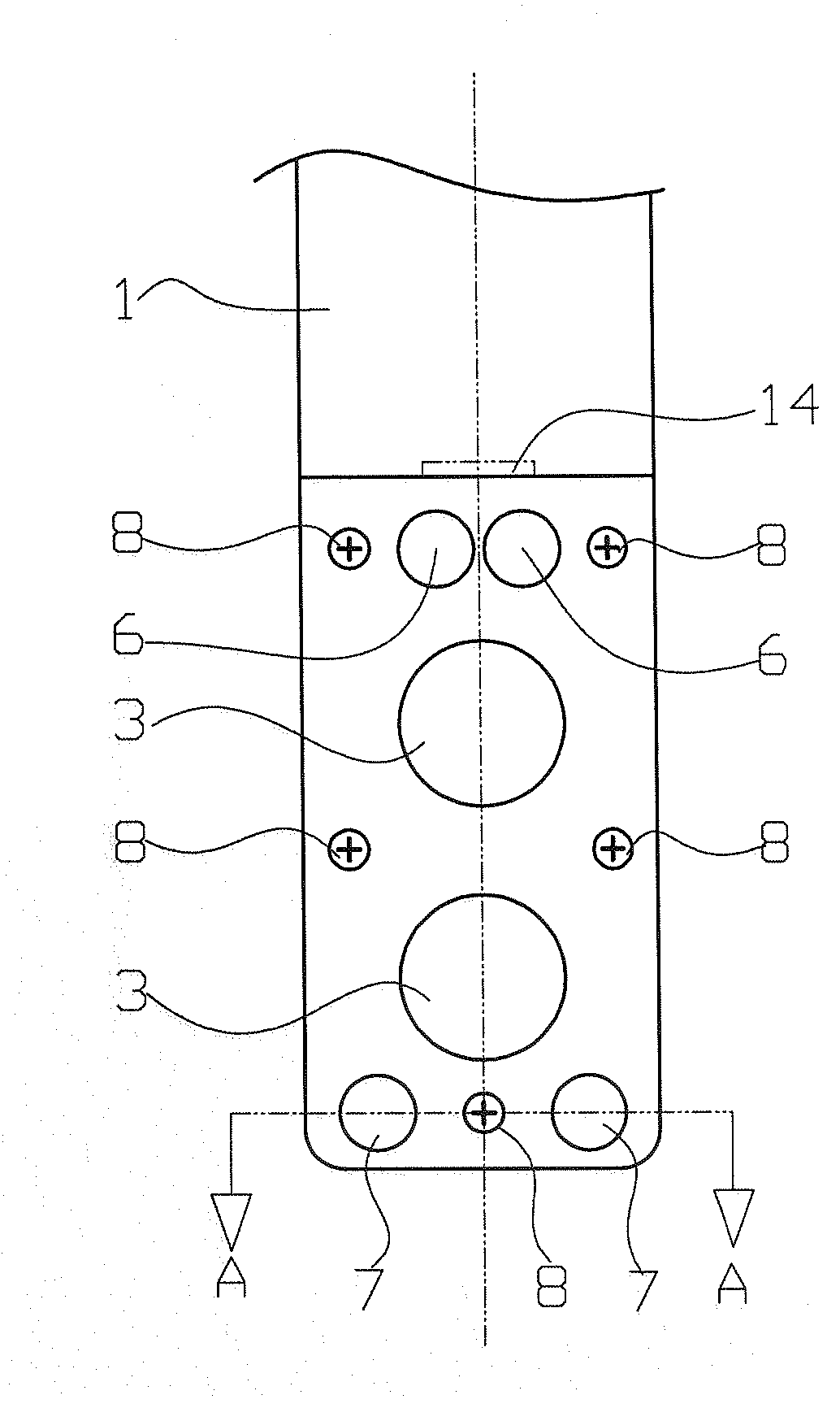
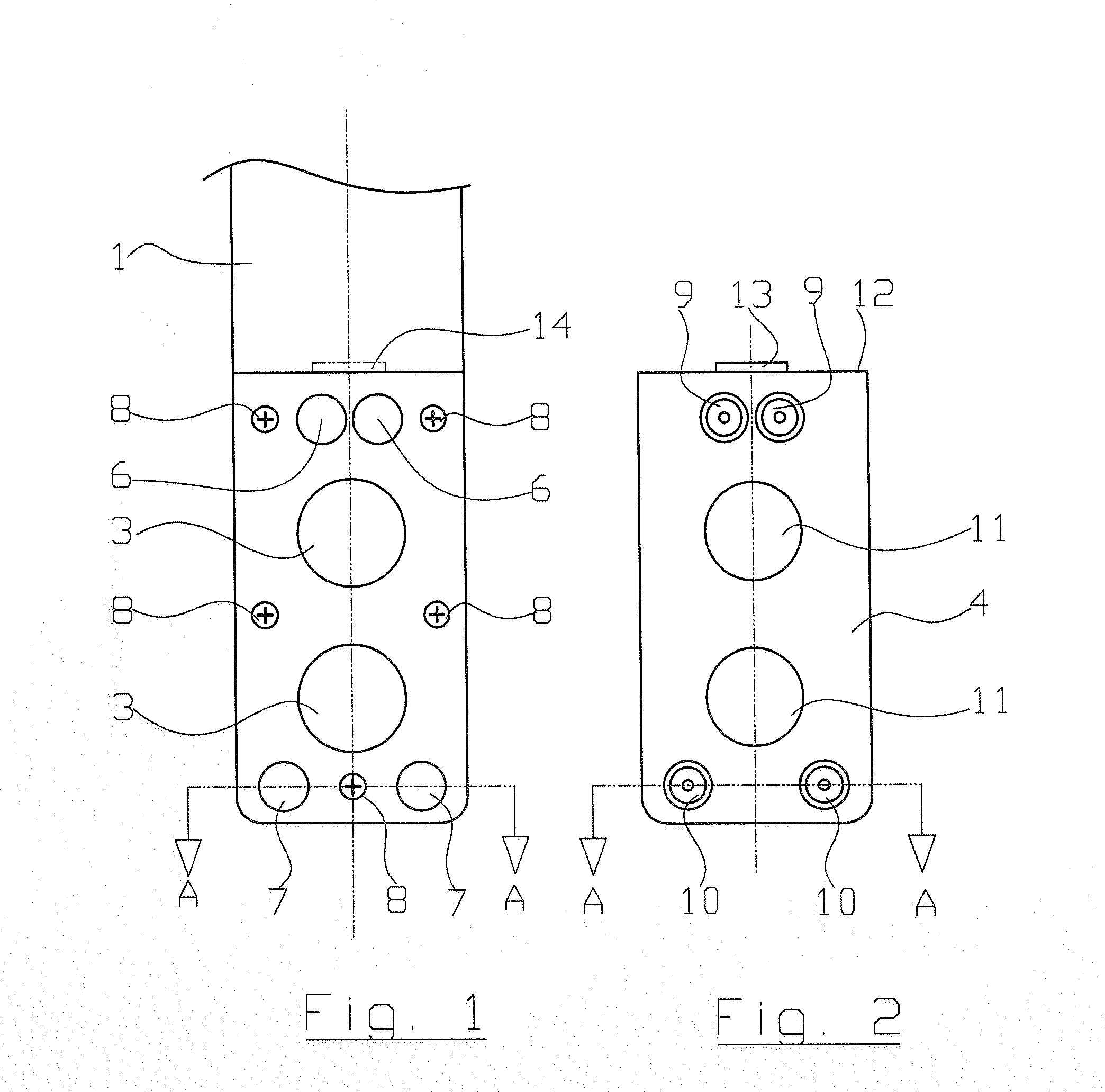
[0014]In FIG. 1 an electronic remote control system 1 is represented partially cut-off, which features a battery compartment 2 into which one or several batteries can be inserted. In the specific case two cylindrical hollow spaces 3 are provided for the reception of so-called button cells. The battery compartment 2 can be closed by means of a cover lid 4. The cover lid 4 for the most part has the shape of a rectangular flat plate that is placed on the battery compartment.

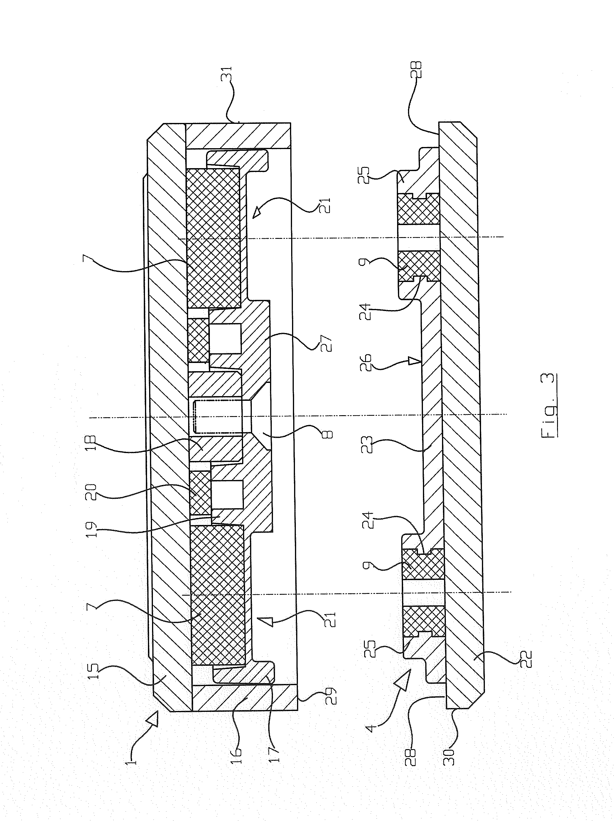
[0015]In the represented embodiment example several permanent magnets 6 and 7 are disposed in the housing of the remote control system in the area of the battery compartment 2, said magnets are pressed into a carrier plate 5 whereby the carrier plate 5 is secured to the housing by means of several screws 8.

[0016]On the cover lid 4, facing the permanent magnets 6 and 7, ferromagnetic counterparts 9 and 10 are disposed that, as will be explained in the context of the FIGS. 3 and 4, are injected into the housing lid. F...


PUM

PropertyMeasurementUnit
circumferenceaaaaaaaaaa
areaaaaaaaaaaa
electrical energyaaaaaaaaaa

Abstract

The remote control system (1) has a battery compartment, which is disposed in a housing and which is closed by means of a removable cover lid (4). The cover lid (4) is held to the housing by means of at least one permanent magnet (6, 7).

Description

REFERENCE TO RELATED APPLICATION[0001]This application claims priority from German application 202009008197.4 filed Jun. 9, 2009, the entire disclosure of which is incorporated by reference.FIELD OF THE INVENTION[0002]The invention concerns a remote control system and, in particular, a remote control system for multi-media devices.BACKGROUND OF THE INVENTION[0003]Remote control systems are provided with batteries with electrical energy, whereby the term “battery” is understood to mean rechargeable batteries also. The remote control systems have a battery compartment, which is disposed in a housing for the purposes of receiving the batteries and which is closed by means of a removable cover lid. It is common to either screw these cover lids onto the housing or to positively attach them using connections, such as through guiding tracks, catch hooks, or such like with the housing so that the cover lid securely closes the battery compartment during normal operation.[0004]In order to exc...

Claims


Application Information

Patent Timeline
Patent Type & Authority Applications(United States)
IPC IPC(8): H01M2/10
CPCH01H9/0235Y02E60/10
Inventor MAIER, FERDINAND
Owner FM MARKETING
Learn More