
Frequency divider using an injection-locking-range enhancement technique

a frequency divider and enhancement technique technology, applied in the field of signal processing, can solve the problems of narrow locking range of the ilfd, limit the application of the ilfd in wide band systems as well as in narrow band systems, and achieve the effect of improving the locking rang

Inactive Publication Date: 2010-12-02
THE HONG KONG UNIV OF SCI & TECH
View PDF5 Cites 18 Cited by
  • Summary
  • Abstract
  • Description
  • Claims
  • Application Information

AI Technical Summary

Benefits of technology

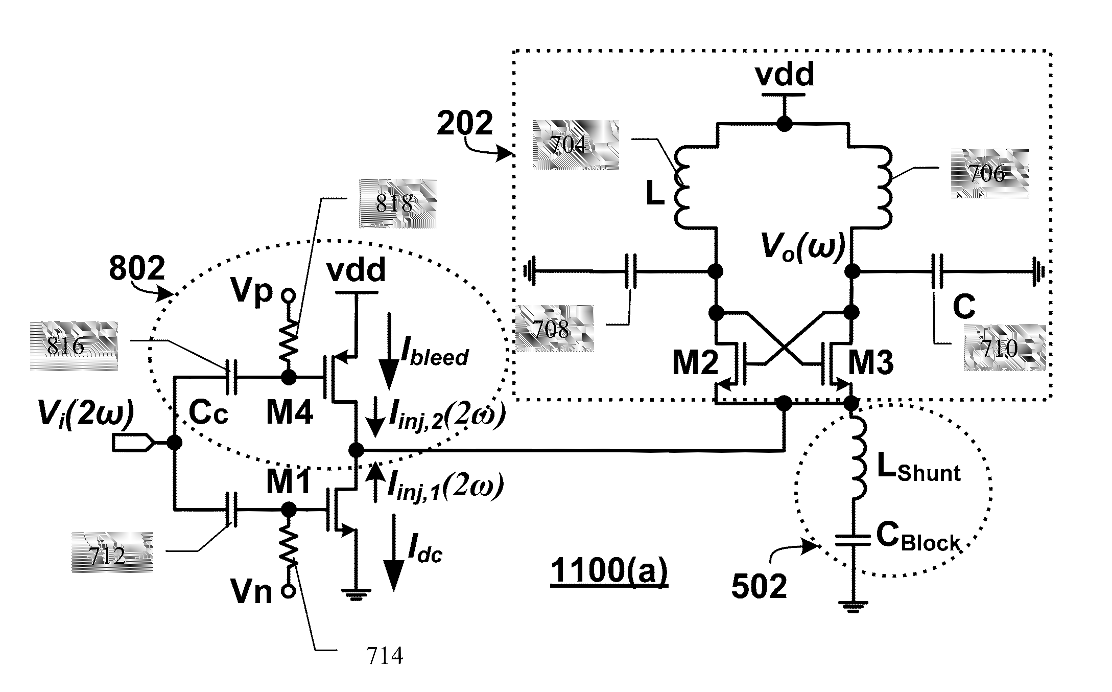
The patent describes an injection-locked frequency divider with injection enhancement that has a locking range. The device includes a biasing circuit, an oscillator, and a current source. The current source provides a bleed current that is reused by a voltage-to-current converter to generate an additional injection current. The method improves the locking range of the device by combining the bleed current with the injection current and the DC current. The technical effect of this patent is to improve the locking range of an injection-locked frequency divider.

Problems solved by technology

However, also due to the high-Q of the resonator, the locking range of the ILFD is narrow.
This further limits the applications of the ILFDs in wide band systems as well as in narrow band systems because of the process, voltage supply and temperature (PVT) variations.

Method used


Image

  • Frequency divider using an injection-locking-range enhancement technique
  • Frequency divider using an injection-locking-range enhancement technique
  • Frequency divider using an injection-locking-range enhancement technique

Examples


Embodiment Construction

[0026]Described herein is a method and system for effectively improving the locking range of a resonator based injection-locked frequency dividers without using area-consuming inductive components. This invention also provides a method and system for improving the response speed and reducing the power consumption of an injection-locked frequency divider. In addition, the invention provides a frequency divider that is structurally simple and can be applied to a wide range of high frequency applications. The following descriptions include several embodiments of the present invention.

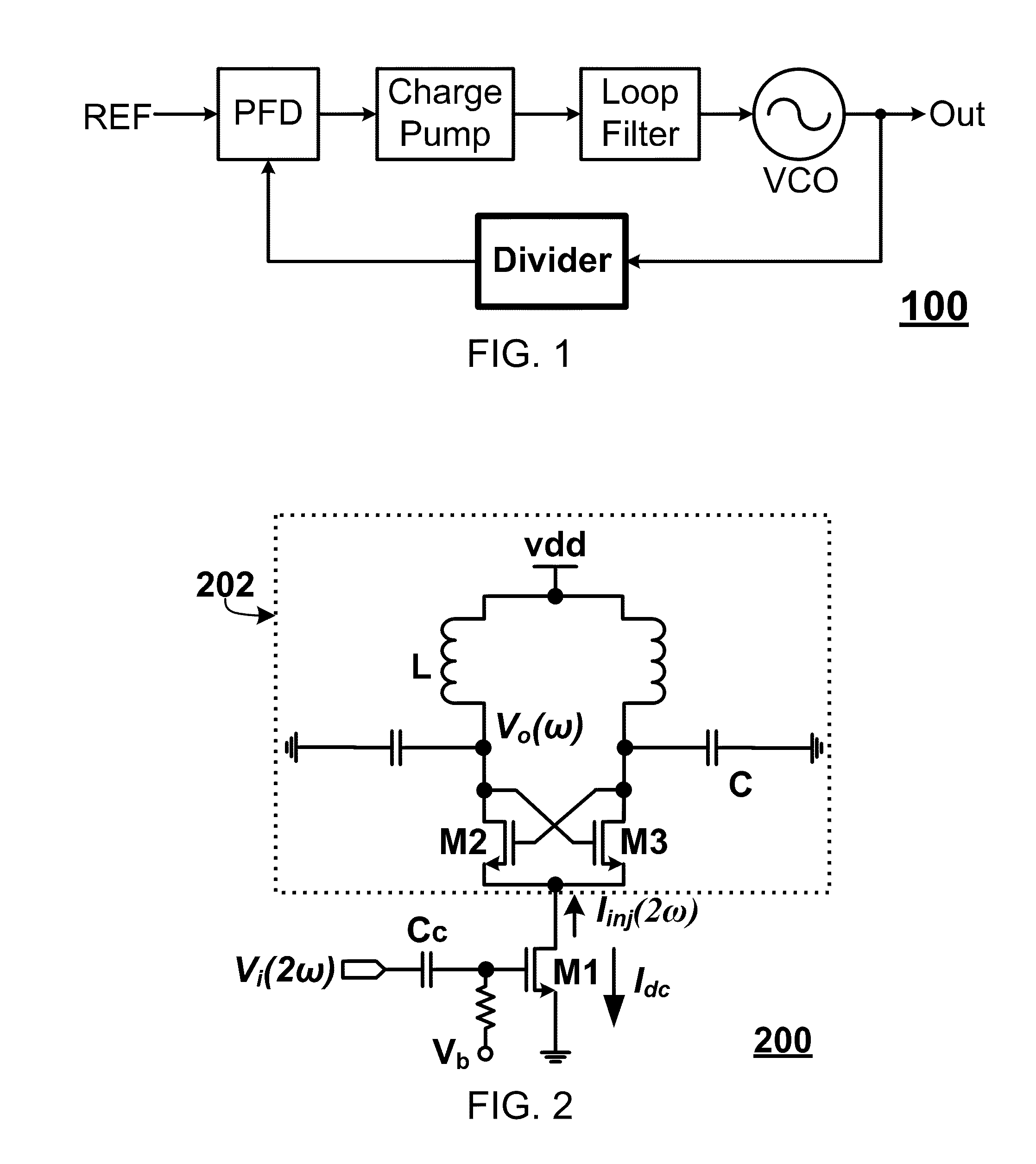
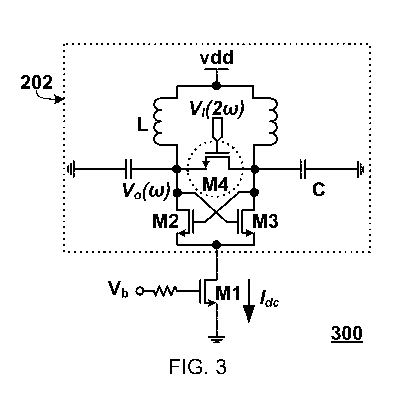
[0027]Referring first to FIG. 2, a basic injection-locked frequency divider is built on an inductor-capacitor (LC) based oscillator 202, where the L and C constitute a high-Q resonator with a peak frequency at ω0. The transistors M2 and M3 form a positive feedback through the cross connection, as a negative trans-conductance (Gm) cell to compensate the loss of LC resonator. The input voltage signal Vi(2ω) ...


PUM


Abstract

A locking range enhancement technique is described that steers away part of the DC current and reuses it to generate more injected AC current to the injection-locked resonator-based frequency dividers (ILFDs). The injection-enhanced ILFDs maintain the key features of ILFDs, which are high speed and low power consumption, without requiring any extra inductive component and thus extra chip area.

Description

TECHNICAL FIELD[0001]The present invention is related to signal processing in general and to injection-locked frequency dividers in particular.BACKGROUND OF THE INVENTION[0002]Frequency dividers are one of the most critical building blocks in wireless and wireless communication systems. They are essential in frequency synthesis, as illustrated in FIG. 1, in a typical frequency synthesizer 100, a frequency divider is used to divide the frequency down from the voltage-controlled oscillator (VCO) and generate a lower frequency signal to be compared with an input high frequency accuracy reference signal, which is normally from a crystal oscillator. With a differential-input, periodic, low phase noise signal source, both in-phase and quadrature-phase periodic differential output signals can be generated by frequency dividers with the phase noise tracking the input signal. The in-phase and quadrature-phase signals are required in zero-IF receivers for modulation or demodulation, and in im...

Claims


Application Information

Patent Timeline
Patent Type & Authority Applications(United States)
IPC IPC(8): H03B5/12
CPCH03B19/00H03L7/24H03L7/18H03L7/099
Inventor LUONG, HOWARD CAMRONG, SUJIANG
Owner THE HONG KONG UNIV OF SCI & TECH
Learn More