Eureka AIR delivers breakthrough ideas for toughest innovation challenges, trusted by R&D personnel around the world.

Main rubber element for hydraulic engine mounts

Active Publication Date: 2010-12-02
VIBRACOUSTIC USA INC
View PDF17 Cites 13 Cited by
  • Summary
  • Abstract
  • Description
  • Claims
  • Application Information

AI Technical Summary

Benefits of technology

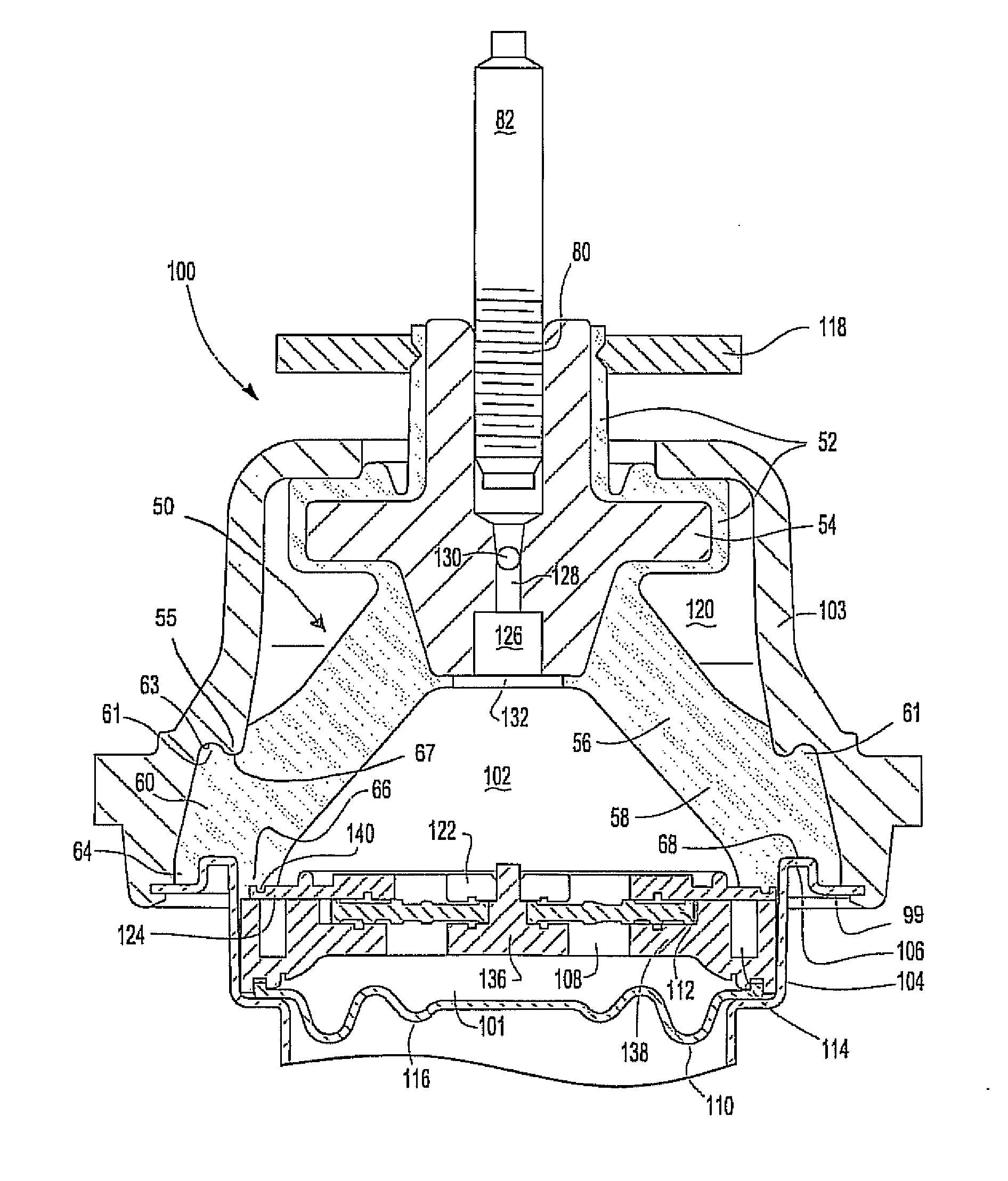
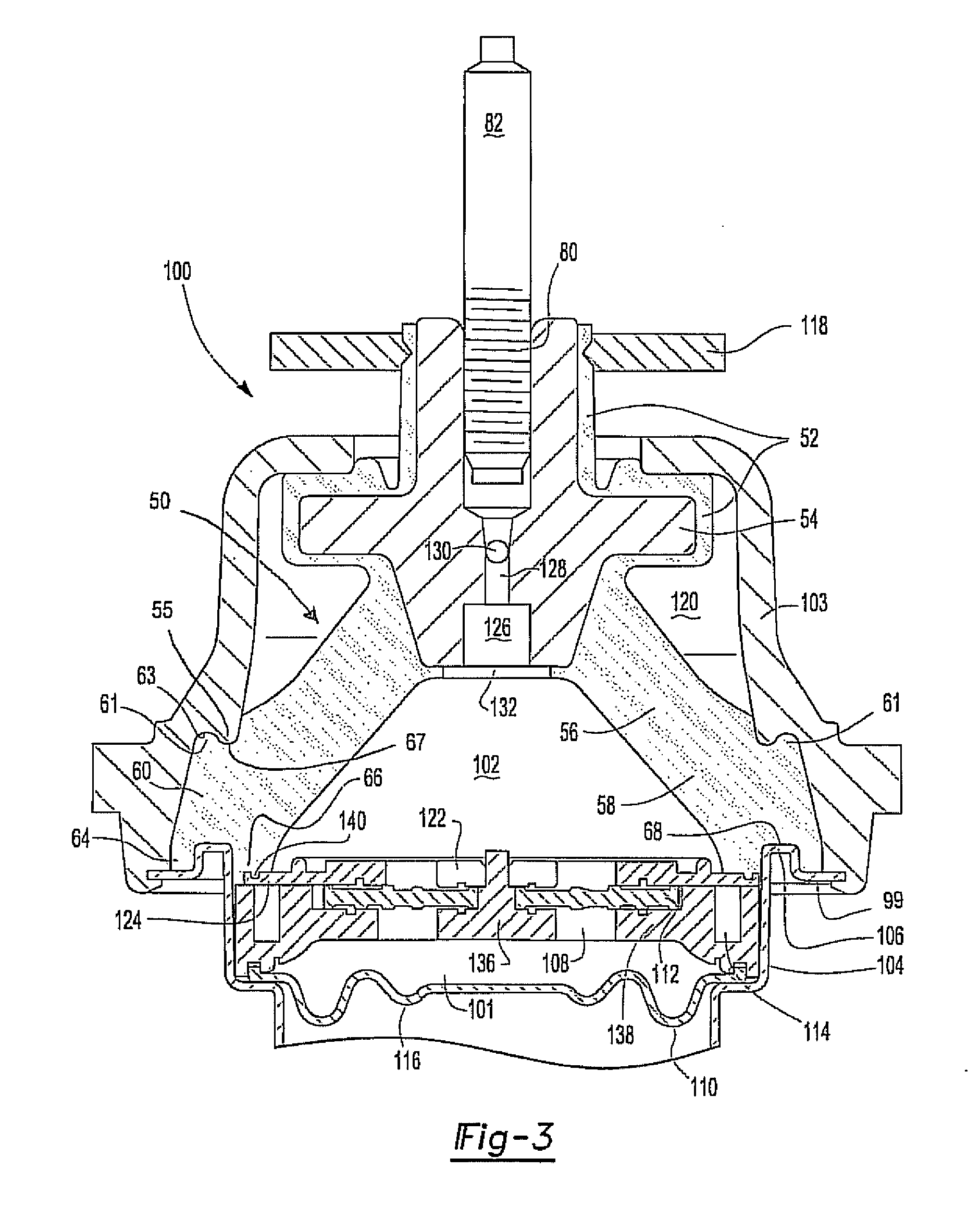
[0006]An improved hydraulic engine mount includes a main rubber element of one piece construction. The main rubber element includes an upper portion, an intermediate portion, and a lower portion. The lower portion includes an interlocking seal portion. The hydraulic engine mount includes an upper housing and a lower housing. The interlocking seal portion includes an upper protrusion operable to fit within an upper groove of the upper housing to fit together to form a tight locking seal. The upper housing further includes an upper protrusion operable to connect to an upper groove of the main rubber element. The upper groove of the main rubber element is annular and extends around the lower portion of the main rubber element. The lower portion of the main rubber element further includes a generally axially extending second protrusion abutting both the upper housing and the lower housing. The lower housing includes a protrusion abutting a second protrusion of the main rubber element and fitting within a second groove of the main rubber element. A third protrusion of the main rubber element abuts the protrusion of the lower housing, a top plate of an inertia track assembly, and defines the lower section of an upper chamber. Additionally, a sealing bead is molded to the bottom of the main rubber element to seal against the top of the inertia track. The grooves and protrusions of the main rubber element define the elements of the interlocking seal and provide improved sealing characteristics as well as increased ease of installation.

Problems solved by technology

Additionally, the outer ring increases complication of assembly to ensure the outer ring is properly sealed.

Method used


Image

  • Main rubber element for hydraulic engine mounts
  • Main rubber element for hydraulic engine mounts
  • Main rubber element for hydraulic engine mounts

Examples


Embodiment Construction

[0011]An improved hydraulic engine mount includes a main rubber element of one piece construction. The main rubber element includes an upper portion, an intermediate portion, and a lower portion. The lower portion includes an interlocking seal portion. The hydraulic engine mount includes an upper housing and a lower housing.

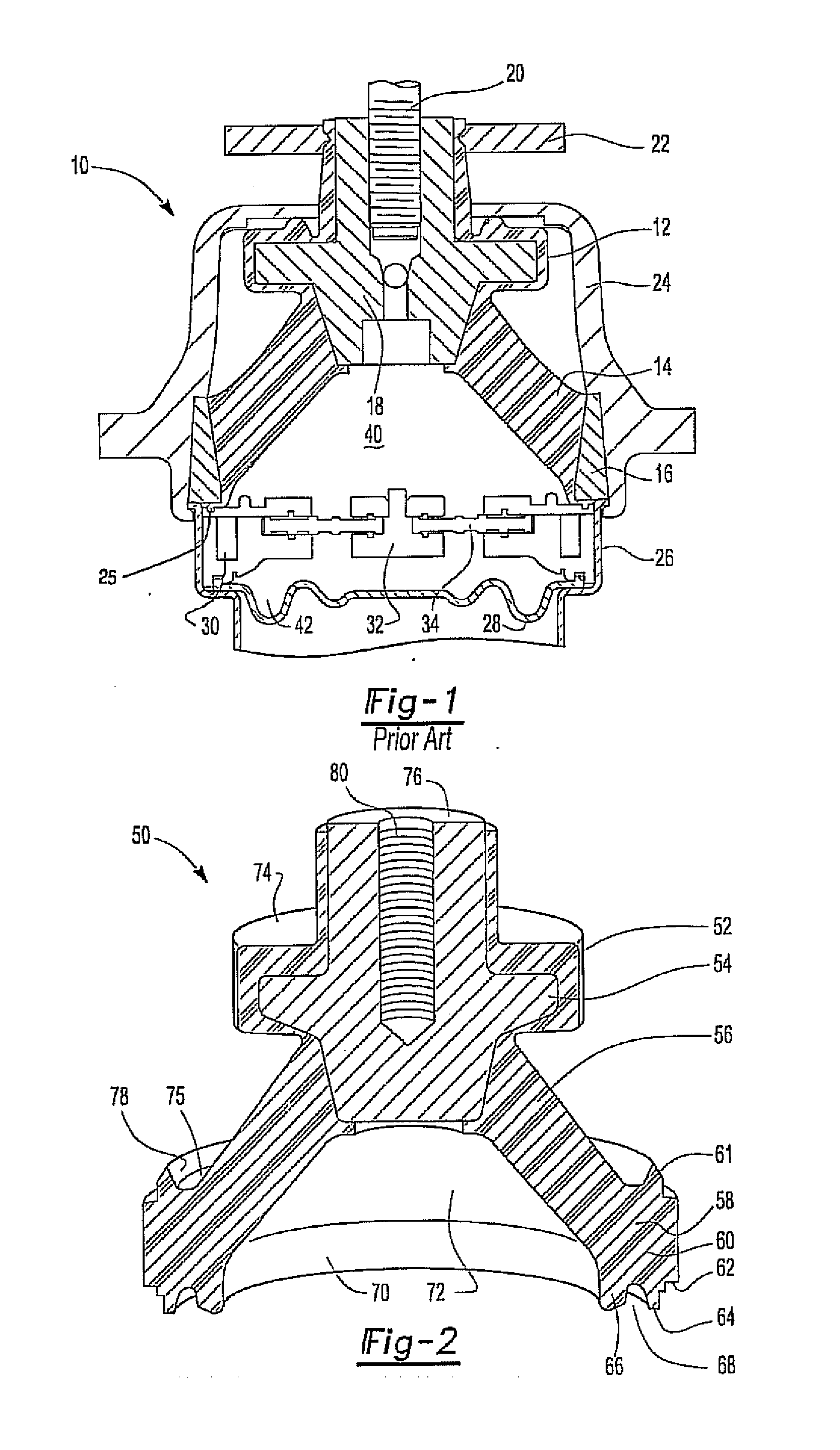
[0012]Previously known hydraulic engine mounts 10 include an upper housing 24 mounted to a lower housing 26, as shown in FIG. 1. A threaded stud 20 for mounting the engine extends from the top of the hydraulic engine mount. A rubber bumper 22 is provided at the top of the hydraulic engine mount for further support a mounted engine. The threaded stud 20 is inserted into a threaded aperture of a core 18 of the main rubber element 12. The main rubber element 12 includes the core 18 and the outer ring 16. The main rubber element 12 is made of a highly elastic rubber. The outer ring 16 rests on top of the lower housing 26.

[0013]The outer ring 16 rests on top of the lo...


PUM


Abstract

An improved hydraulic engine mount includes a main rubber element of one piece construction. The main rubber element includes an upper portion, an intermediate portion, and a lower portion. The lower portion includes an interlocking seal portion. The hydraulic engine mount includes an upper housing and a lower housing. The interlocking seal portion includes an upper protrusion operable to fit within an upper groove of the upper housing to fit together to form a tight locking seal. The upper housing further includes an upper protrusion operable to connect to an upper groove of the main rubber element. The upper groove of the main rubber element is annular and extends around the lower portion of the main rubber element. The lower portion of the main rubber element further includes a generally axially extending second protrusion abutting both the upper housing and the lower housing. The lower housing includes a protrusion abutting a second protrusion of the main rubber element and fitting within a second groove of the main rubber element. A third protrusion of the main rubber element abuts the protrusion of the lower housing, a top plate of an inertia track assembly, and defines the lower section of an upper chamber. Additionally, a sealing bead is molded to the bottom of the main rubber element to seal against the top of the inertia track.

Description

CROSS-REFERENCE TO RELATED APPLICATIONS[0001]This application claims priority of U.S. Provisional Patent Application Ser. No. 61 / 181,039 filed May 26, 2009, which is incorporated herein by reference.FIELD OF THE INVENTION[0002]This invention relates generally to engine mounts. More particularly, this invention relates to a hydraulic engine mount having a main rubber element.BACKGROUND OF THE INVENTION[0003]Hydraulic engine mounts are used to position an engine and to control the gross motion of the engine within a vehicle. The hydraulic engine mount also provides damping to absorb energy created by the moving engine by a large amplitude excitation (±1.0 millimeter) and to provide isolation so that vibration of an engine does not transfer to the vehicle structure by small amplitude excitation (±0.1 millimeter). As shown in FIG. 1, previously known engine mounts include an upper mounted housing and a lower housing. A threaded stud for mounting the engine extends from the top of the ho...

Claims


Application Information

Patent Timeline
IPC IPC(8): F16F13/08F16F13/00F16M5/00F16F13/16
CPCF16F13/108
Inventor GARETY, JOHNHUGHES, ERICMOLESWORTH, TROY
Owner VIBRACOUSTIC USA INC
Why Eureka
Eureka Blog
Learn More