
Electroporation device for improved electrical field control

a technology of electroporation device and electrical field control, which is applied in the field of electroporation device and a method, can solve the problems of increasing length difficulty in achieving the effect of uniform field, and enhanced field geometries based on placement of terminal ends of multiple electrotherapeutical devices in two or three directions

Inactive Publication Date: 2010-11-25
REGION HOVEDSTADEN VHERLEV HOSPITAL
View PDF10 Cites 7 Cited by
  • Summary
  • Abstract
  • Description
  • Claims
  • Application Information

AI Technical Summary

Benefits of technology

[0026]There is thus a need for an electroporation device and an electroporation method that overcomes the shortcomings of the presently known devices and methods. It is an object of the present invention to provide such a device and method. It is a further object of the invention to provide an electroporation device which can be manoeuvred to deeper-lying regions of the body or to regions that are otherwise difficult to access, and to do so with the least amount of injury to the tissue. E.g. for applications in the brain, it is an objective to provide a device requiring the smallest possible entry hole while providing the largest possible electric field. A further object of the invention is to provide an electroporation device capable of delivering an improved, flexible and more efficient electric field in order to enhance the transfer of e.g. drugs, isotopes, genetic materials or other therapeutic molecules through cell membranes of a target tissue / region. By providing an improved, more efficient and more readily controlled electrical field, the energy applied through electrodes to the tissue may be reduced. Thereby, unintended damages to the tissue, especially the tissue immediately surrounding the electrodes may be reduced.
[0027]An objective of the present invention is therefore to provide an electrode tip / electrotherapeutic device tip design that is configured to minimize the creation of hot-spots in living tissue during the application of electric fields to said tissue.
[0028]Another objective of the present invention is to provide an electrode / electrotherapeutic device geometry that is configured to minimize the trauma inflicted on intervening tissue during insertion and, if applicable, continued presence, of the electrodes.

Problems solved by technology

In the treatment of diseases in the brain, e.g. brain cancer, as well as diseases in other anatomical areas of a body, physical access to a diseased tissue region may be a challenge.
Furthermore, efficient delivery and subsequent uptake of therapeutic molecules, such as a drug or genetic compound, to an anatomical target tissue is often a problem.
Furthermore, maintaining control with the paths of individual needle-type electrodes as they traverse intervening tissues that may have different morphologies is a challenge that increases with the length of insertion.
The distance between electrodes is a critical parameter in the creation of an electric field with desired characteristics, and the possible, uncontrolled deviations from desired paths that may result from deep insertions may substantially affect field homogeneity and resulting drug uptake.
Yet further, a large access area must be available for the insertion of said arrays, and specifically for applications in the brain this will entail creating an excessively large hole in the patient's skull.
Therefore, it is evident that the mentioned prior art devices are only well-suited for treatment in target regions in close proximity to an outer surface of the body, because an attempt to treat deeper-lying regions would cause excessive trauma to the intervening tissue.
This is especially an issue in minimally invasive approaches, where there is often a trade-off between the desire for the largest possible transmitting surface and the constraints that are imposed by small working spaces and the desire to minimize damage to intervening and adjacent tissue during applicator insertion.
These hot-spots are associated with local cell death—i.e. necrosis—when they occur in tissue that is to be treated, and are detrimental to the effects of some treatments especially in the field of electroporation.
While this approach is well suited to surface applications, the use of plates becomes problematic for minimally invasive applications where the placement of plates is frequently a challenge, and where excessive damage may be inflicted to intervening tissue.
However, for applications to sensitive tissues—such as neurological or cardiac tissues—hot-spots and resulting tissue necrosis may result in the loss of important tissue functions.
Another unaddressed issue with needle electrode applicators is the cutting or piercing of tissue that takes place during electrode applicator insertion.
Yet another unaddressed issue with currently available electrode applicators is the lack of control over field distribution.
This is less problematic in treatments that are meant to target the skin or tissue residing immediately below the skin, but becomes problematic once an operator desires to treat deeper-lying tissue regions.
A related issue regards the ability of currently available electrode applicators to generate precisely defined, three-dimensional electric fields that may be configured to conform to the three-dimensional contours of a particular tissue region—e.g. a tumour.
Such single-plane electrode applicators are less well suited to the generation of complex, potentially irregular and possibly three-dimensional fields that may be optimal for minimally invasive applications.
While such a configuration is perceived as superior in providing fields that may conform to individual lesion anatomies, parameters of the field that is applied to the target tissue are still severely affected by the pointed shapes of electrode distal ends and especially by the positions of said electrodes and their distal ends relative to one another.
Another issue that is related to the pointed shape of the distal ends of currently available electrode applicators is the lack of transmission surface scalability that is associated with this particular shape.
However, the problematic hot-spot effect remains due to the constant geometry of a pointed tip.
This limits the ability of currently available electrode applicators to transfer electric fields at their distal ends.
In this process, burning / scarring of target and / or adjacent tissue is strongly undesirable, since it may interfere with the uptake of molecules through changes in tissue conductivity.

Method used


Image

  • Electroporation device for improved electrical field control
  • Electroporation device for improved electrical field control
  • Electroporation device for improved electrical field control

Examples


Embodiment Construction

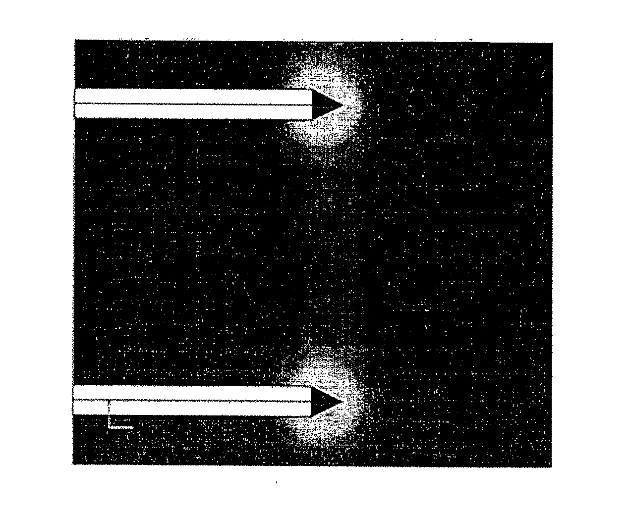
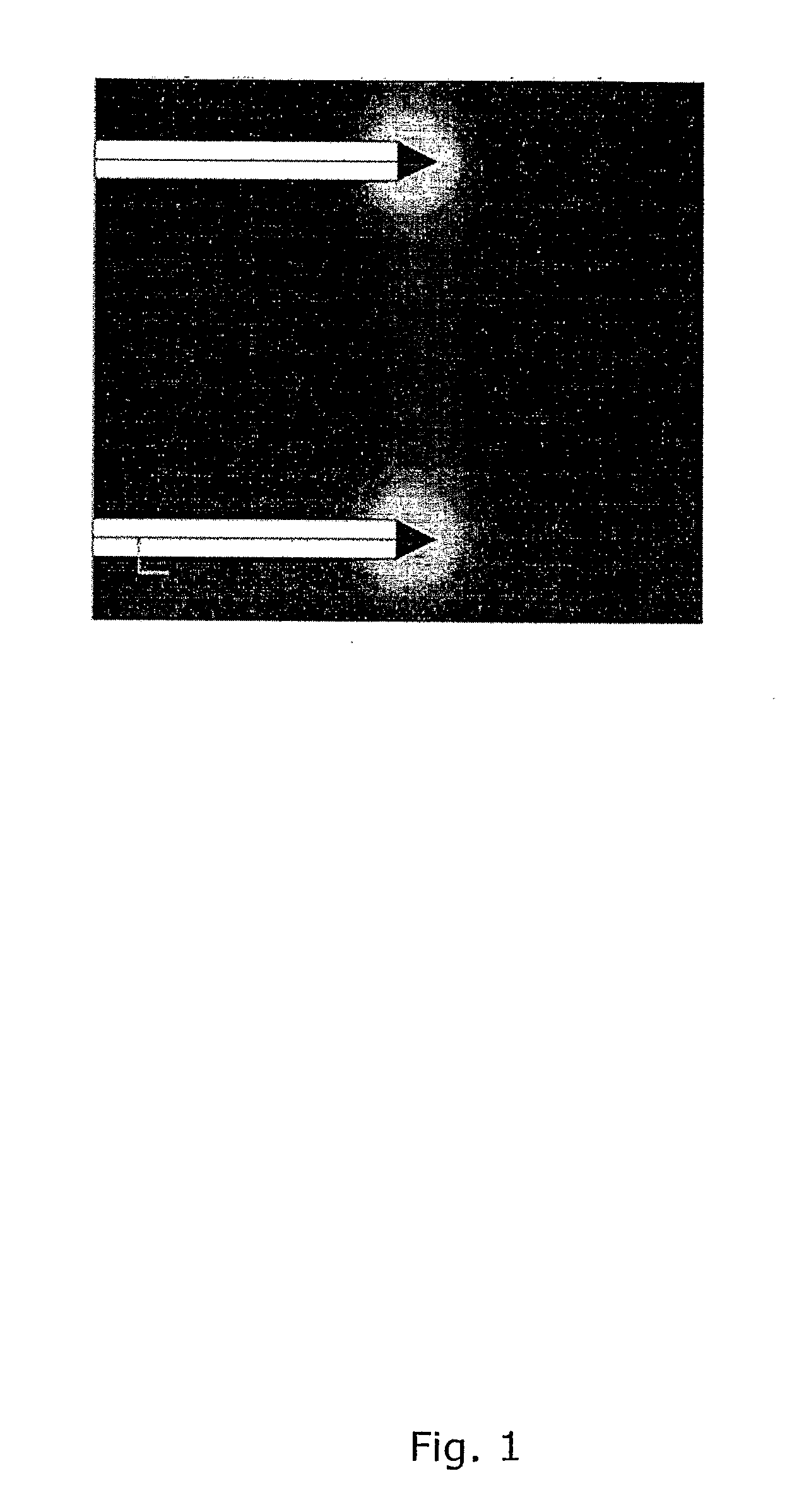
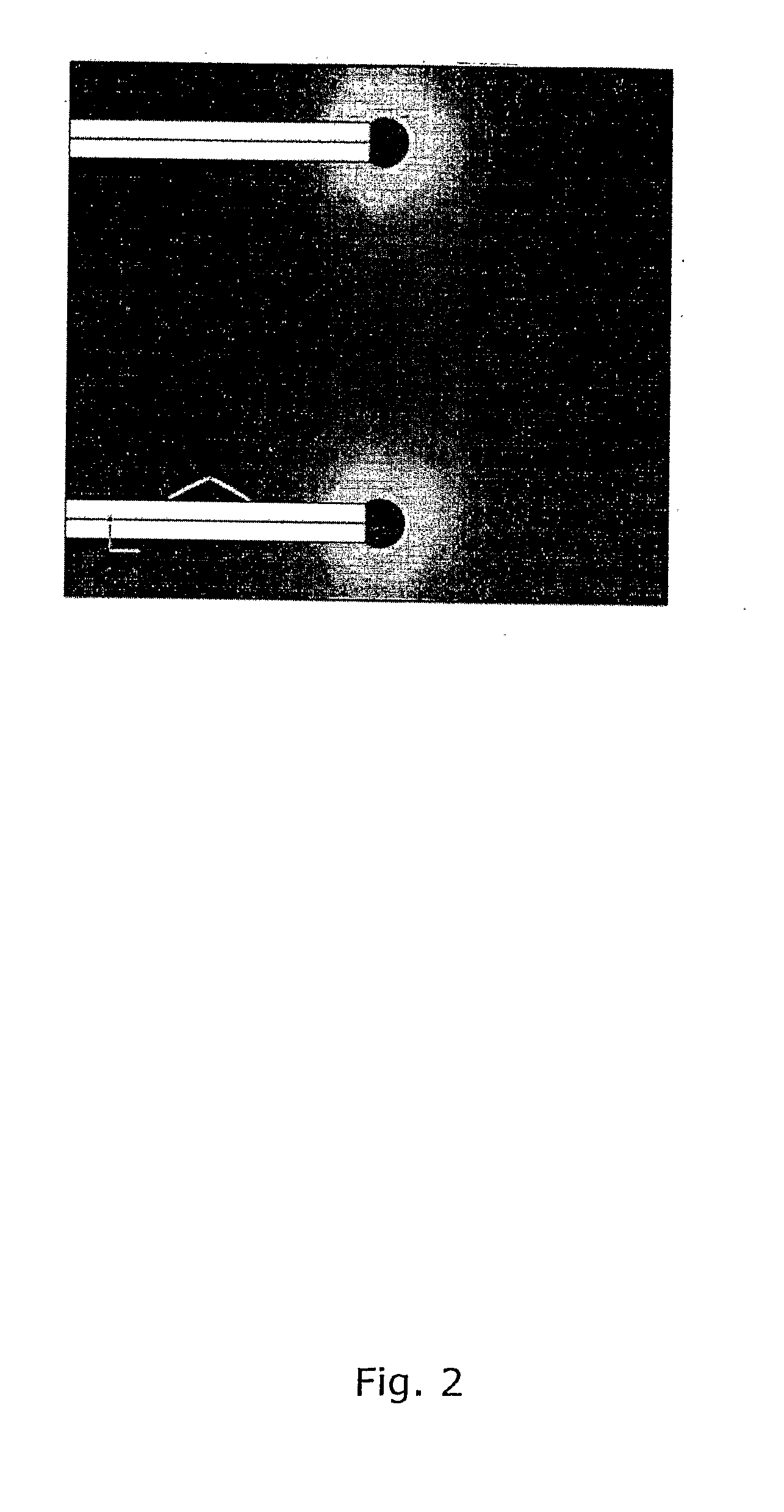
[0143]FIGS. 1 and 2 shows the resultant electrical field strength computer simulation around two different sets of electrotherapeutic devices with point shaped electrodes (only the tips are un-insulated) of an electrical pulse between poles of the electrotherapeutic devices, the test being performed by the inventors. FIG. 1 shows the electrical field induced by a set of prior art electrotherapeutic devices having pointed ends. Around the edges and points provided by the angles between the surfaces of the electrodes, so-called hot spots of high intensive energy are created, which will create a burning or scarring of the tissue in the region of the hot spot. In ablation procedures this is not so relevant because the purpose is to cause cell death. However in electroporation this may be highly undesirable, since cell death in itself may be undesirable, or because it may change the electric properties of the tissue, making it difficult to control the process of applying the field. In FI...


PUM


Abstract

An electroporation device and method having a plurality of electrotherapeutic devices for insertion into and surrounding a sensitive target tissue e.g. the brain of a patient where the electroporation device and the electrotherapeutic devices are adapted for applying a precisely controlled electrical field, and to avoid or limit damages to the healthy tissue surrounding the target tissue to be treated.

Description

FIELD OF THE INVENTION[0001]The present invention concerns a device and a method for electroporation, in general and more specifically the present invention concerns a device and method for administering therapeutic molecules, such as a drug, an isotope or genetic material, enhanced by electric pulses causing electroporation of and / or electrophoretic effects in a target region of a patient's body. More particularly the invention relates to a device and method wherein a plurality of electrodes / electrotherapeutic devices are inserted into or into the vicinity of a target tissue for applying an electrical field for opening cell membranes in that tissue, and where a dose of therapeutic molecules is administered to that target tissue.[0002]More specifically the invention relates to a device and a method for performing electroporation in deeper-lying tissues of the body of a patient. More specifically the invention relates to a device and a method that may be applied for electroporation i...

Claims


Application Information

Patent Timeline
Patent Type & Authority Applications(United States)
IPC IPC(8): A61N1/18
CPCA61N1/306A61N1/327A61N1/325
Inventor GEHL, KAREN JULIESTAAL, LASSE GULDBORG
Owner REGION HOVEDSTADEN VHERLEV HOSPITAL
Learn More