
Radiography device

Inactive Publication Date: 2010-11-25
SHIMADZU CORP
View PDF0 Cites 2 Cited by
  • Summary
  • Abstract
  • Description
  • Claims
  • Application Information

AI Technical Summary

Benefits of technology

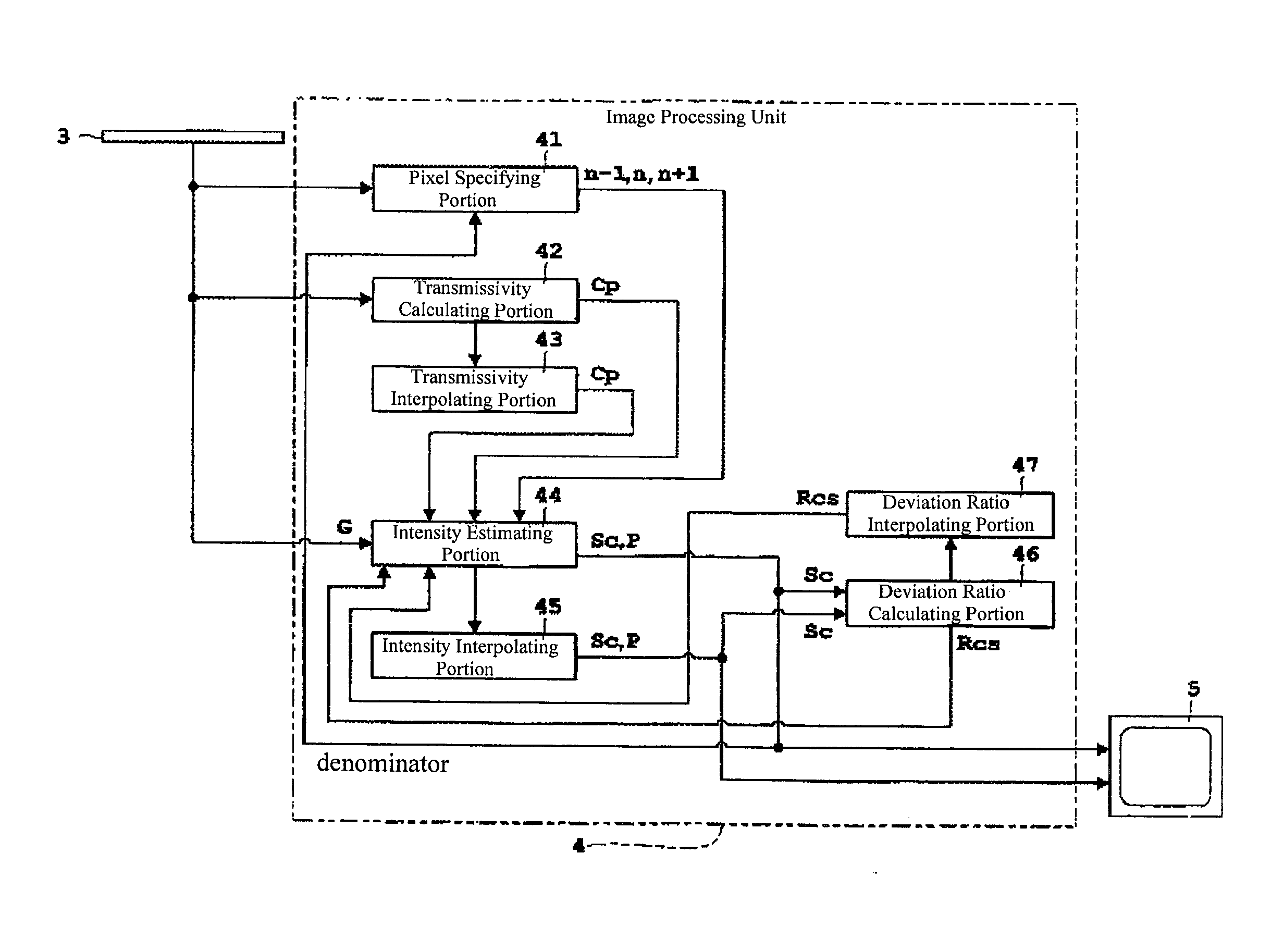
[0016]In the invention set forth in claim 1, radiation is emitted from radiation emitting means, and is incident into the radiation detecting means through the scattered radiation removing means. A portion of the scattered radiation is removed by the scattered radiation removing means, and the radiation is detected by the radiation detecting means, to produce a radiation image. At this time, of the individual pixels that structure the radiation image, particular pixels are specified by the pixel specifying means. The scattered radiation intensities of the particular pixels specified by the pixel specifying means, and / or the direct radiation intensities of the particular pixels are estimated by the intensity estimating means. Consequently, it is possible to estimate appropriately the scattered radiation intensities and / or the direct radiation intensities at the particular pixels, taking into consideration the status of installation of the scattered radiation removing means. On the other hand, for those pixels that have not been specified, the following is performed. Based on the scattered radiation intensities and / or the direct radiation intensities estimated by the intensity estimating means, interpolation is performed by the intensity interpolating means for radiation intensities that are the scattered radiation intensities for pixels that have not been specified or the direct radiation intensities for the pixels that have not been specified. Consequently, for specified pixels, the radiation intensity is estimated by the intensity estimating means, and for pixels that have not been specified, the radiation intensity is interpolated by the intensity interpolating means. A radiation image can the be obtained appropriately based on such radiation intensities, and the shadows of the scattered radiation removing means are eliminated to produce a radiation image of only the direct radiation, from which the scattered radiation has been completely removed. In the radiation images that can be obtained by these pixel specifying means, the intensity estimating means, and the intensity interpolating means, can be obtained appropriately with any scattered radiation removing means, without depending on any particular scattered radiation removing means (for example, a synchronized grid). The result is the possibility of application also to general-use scattered radiation removing means, making it possible to obtain an appropriate radiation image, independently of the status of installation of the scattered radiation removing means. Additionally, it is not necessary to estimate the radiation intensities for all of the pixels, but rather only the radiation intensities for specified particular pixels need be estimated and the radiation intensities of the remaining pixels that were not specified may be calculated through performing interpolation, and thus there is the effect of being able to reduce and shorten the time required by the calculation processing.
[0043]The radiography device according to the present invention makes it possible to obtain an appropriate radiation image, independently of the status of installation of scattered radiation removing means, through enabling the application to even general-use scattered radiation removing means through: the pixel specifying means specifying particular pixels from among the pixels that structure a radiation image; the intensity estimating means estimating radiation intensities that are scattered radiation intensities of particular pixels that are specified by the pixel specifying means and / or direct radiation intensities of the specified pixels; and, based on the radiation intensities that are the scattered radiation intensities and / or the direct radiation intensities, estimated by the intensity estimating means, the intensity interpolating means interpolating radiation intensities that are the scattered radiation intensities of pixels that have not been specified and / or the direct radiation intensities of pixels that have not been specified.

Problems solved by technology

However, even when a grid is used, a false image is formed by the scattered radiation that passes through the grid, and a false image is formed by the absorbing foil that forms the grid.
While, at present, in methods that perform image processing that includes smoothing, and the like, for correcting the moire fringes, there is a tendency to have a reduction in the resolution of the direct x-rays (hereinafter termed the “direct radiation”) when there is excessive correction of false images.
Because of this, it is difficult to perform adequate processing on the false images.
Furthermore, while there have been a variety of methods proposed as methods for making corrections for the scattered radiation that remains even when a grid is used, there is a problem in that the correction calculations are time-consuming.
Because the absorption and attenuation thereby is not taken into account, it is possible that there will be an error in the evaluation of the estimated direct radiation intensities for all of the pixels, including the blocked pixels.
Consequently, there is the danger that, conversely, false images will be produced through error in the scattered radiation intensity distribution due to the effect thereof
Consequently, there is a high likelihood that there will be error in the scattered radiation intensity distribution calculated in the correction calculations.
Furthermore, it is necessary to be within the requirements for the deformation for the absorbing foil that structures the grid, and for the misalignment from the design position, and thus there are tight requirements for the mechanical precision and assembly precision, which are difficult to achieve from a cost perspective and technology perspective.

Method used


Image

  • Radiography device
  • Radiography device
  • Radiography device

Examples


Embodiment Construction

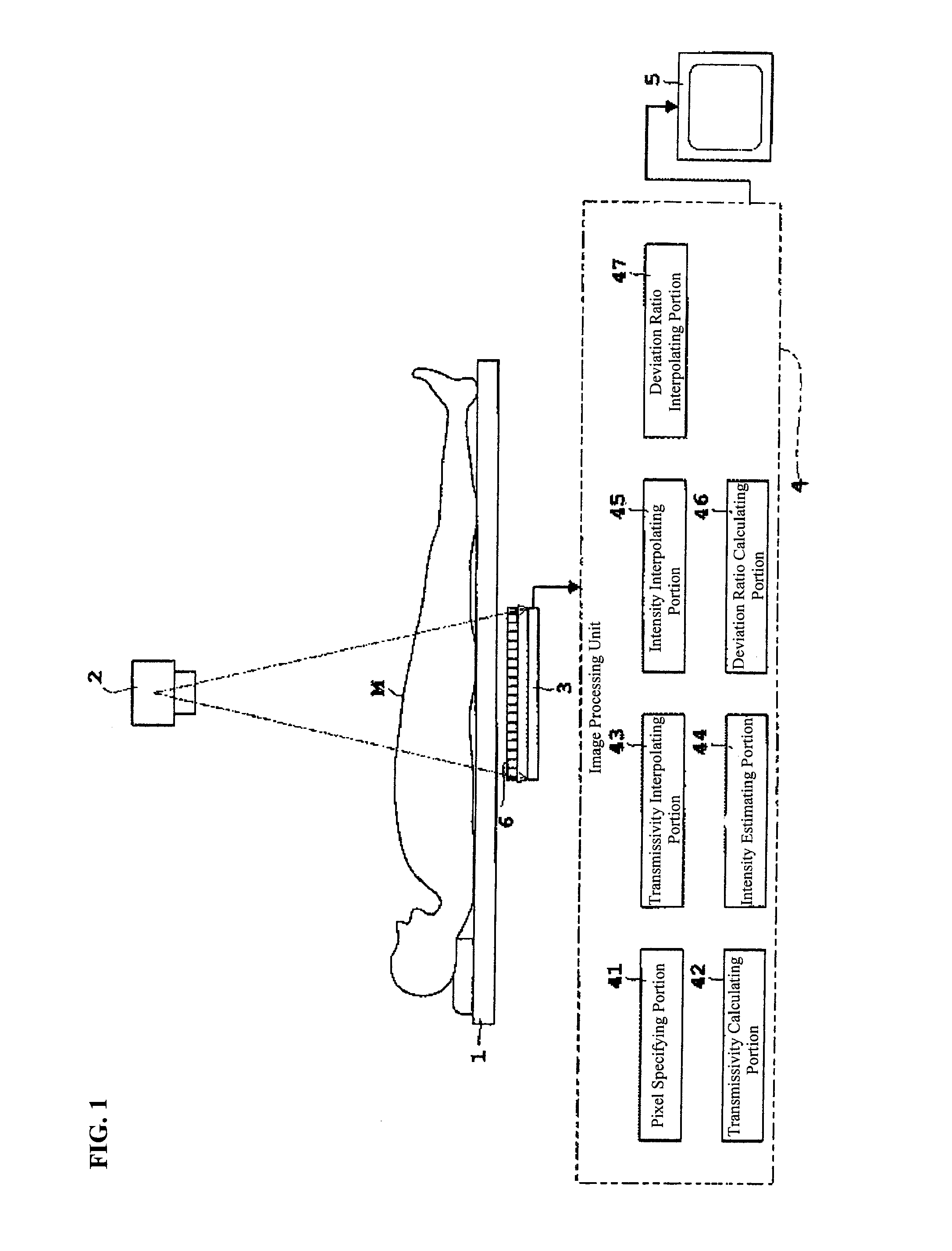
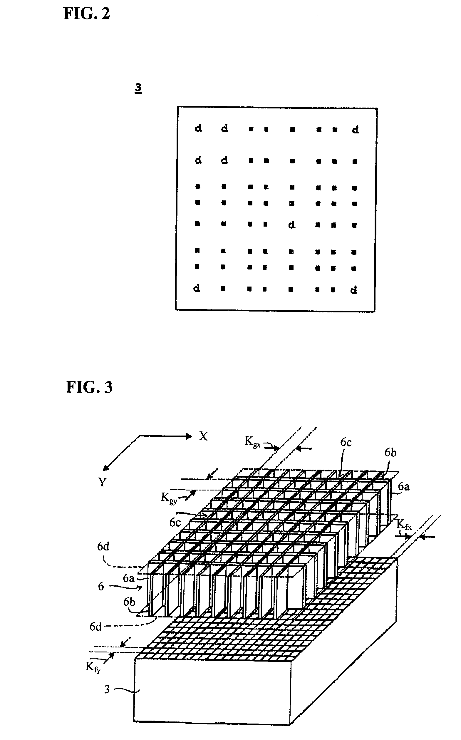
[0054]A first example of embodiment according to the present invention will be explained below referencing the figures. FIG. 1 is a block diagram of an x-ray radiography device according to the first example of embodiment, including the second example of embodiment, described below; FIG. 2 is a schematic diagram of a detecting surface of a flat panel-type x-ray detector (FPD); and FIG. 3 is a schematic diagram of a synchronized cross grid. Moreover, in the first example of embodiment, which includes the second example of embodiment, described below, x-rays will be used in the explanation as an example of the radiation.

[0055]The x-ray radiography device as set forth in the first example of embodiment, which includes the second example of embodiment, described below, as illustrated in FIG. 1, includes: a ceiling plate 1 upon which is placed a test subject M; an x-ray tube for emitting an x-ray in the direction of the test subject M; a flat panel x-ray detector (hereinafter termed an “...


PUM


Abstract

A radiography device that can be applied to even general-purpose scattered radiation removing means, capable of producing appropriate radiation images that are independently of the status of installation of scattered radiation removing means. A pixel specifying portion specifies particular pixels of the various pixels that comprise an x-ray image. An intensity estimating portion estimates the scattered x-ray intensities (scattered radiation intensities) at the particular pixels specified by the pixel specifying portion and / or the direct x-ray intensities (the direct radiation intensities) of the particular pixels. Consequently, it is possible to estimate appropriately the scattered x-ray intensities and / or direct x-ray intensities at the particular pixels in consideration of the status of installation of a grid (scattered radiation removing means).

Description

CROSS REFERENCE TO RELATED APPLICATION[0001]This application is based on Japanese Patent Application No. 2008-014603 filed Jan. 25, 2008, which is incorporated herein by reference.FIELD OF THE INVENTION[0002]The present invention relates to a radiography device that is used in, for example, radiographic x-ray equipment and x-ray CT equipment, and the like, and, in particular, relates to a technology for removing scattered radiation.BACKGROUND OF THE INVENTION[0003]Conventionally, in radiographic x-ray equipment and x-ray computed tomography (CT) for medical use, a grid to remove scattered radiation (scattered radiation removing means) has been used in order to prevent the scattered x-rays (hereinafter termed “scattered radiation”) from the test subject from being incident on the x-ray detector. However, even when a grid is used, a false image is formed by the scattered radiation that passes through the grid, and a false image is formed by the absorbing foil that forms the grid. In p...

Claims


Application Information

Patent Timeline
IPC IPC(8): G01N23/04
CPCA61B6/5282A61B6/4291G21K1/025A61B6/583
Inventor KUWABARA, SHOJI
Owner SHIMADZU CORP
Learn More