
Mechanical oscillator having an optimized thermoelastic coefficient

a mechanical oscillator and thermoelastic coefficient technology, applied in the field of mechanical oscillators, can solve the problems of complex implementation of methods, inability to adapt to different types of balances, and low sensitivity to thermal variations

Active Publication Date: 2010-11-18
MFG & FAB DE MONTRES & DE CHRONOMETRES ULYSSE NARDIN LE LOCLE SA
View PDF8 Cites 20 Cited by
  • Summary
  • Abstract
  • Description
  • Claims
  • Application Information

AI Technical Summary

Benefits of technology

[0007]Another object of the present invention is to propose reliable and precise mechanical oscillators the design and manufacture of which are simplified.
[0012]Furthermore Young's modulus is higher for a spiral engraved along the crystallographic axis {1,1,1} than the average module for an engraving along the crystallographic axis {1,0,0}. Thus, for a spiral spring of the same winding, the spiral spring engraved along the crystallographic axis {1,1,1} will be able to be finer and thus lighter. This makes it possible to reduce the mass of the spiral spring and thus the variations in operation as a function of the position.
[0030]The method in accordance with the invention thus makes it possible in an advantageous way to compensate the thermal drift of the balance with the aid of the spiral spring, in particular for a balance spiral torque of quality 1, corresponding to a temperature coefficient less than or equal to + / −0.6 s / j / deg.
[0031]The growth of a layer of oxide on a silicom oriented along the crystallographic axis {1,1,1} is achieved by process of damp oxidation and allows rendering positive the temperature coefficient for the spiral spring and obtaining a variation, as a function of the temperature, of the resilient torque of the spiral spring, compensating the variation as a function of the temperature of the moment of inertia of the balance. Thus it is no longer necessary to make tend toward zero the temperature coefficient of the spring constant of the spiral in order to minimize the thermal drift of the oscillator according to the invention. It must then be possible to achieve in a simple way a particular spiral spring, for a given balance, characterized by predetermined physical parameters such as its mass, its moment of inertia, its material, its radius of gyration and its coefficient of expansion.

Problems solved by technology

Such a method has, on the one hand, a complexity in its implementation.
On the other hand, the spiral springs produced according to this method (i.e. the spiral springs optimized toward a temperature coefficient of zero) do not allow adaptation to different types of balances.

Method used


Image

  • Mechanical oscillator having an optimized thermoelastic coefficient
  • Mechanical oscillator having an optimized thermoelastic coefficient
  • Mechanical oscillator having an optimized thermoelastic coefficient

Examples


Embodiment Construction

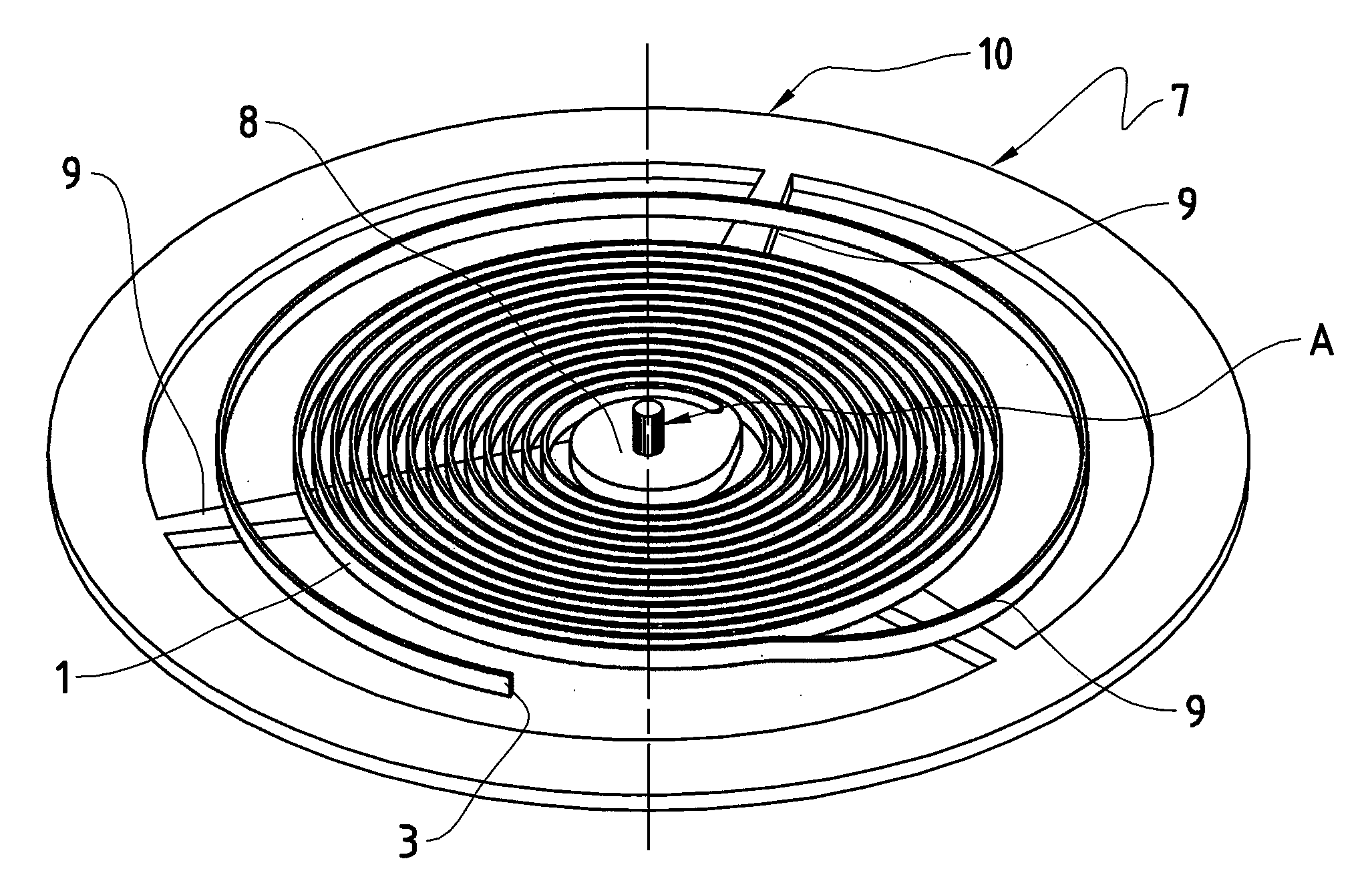
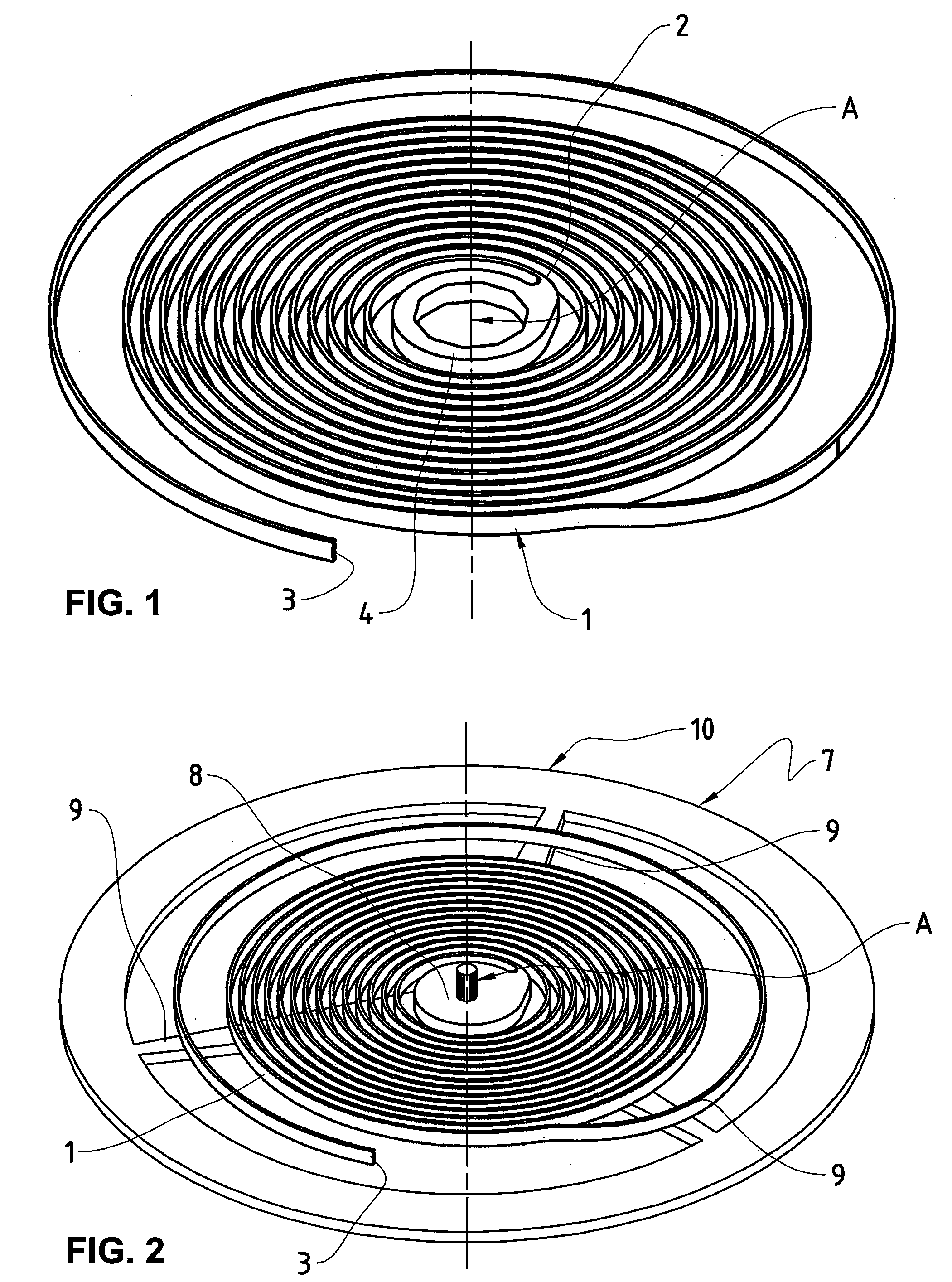
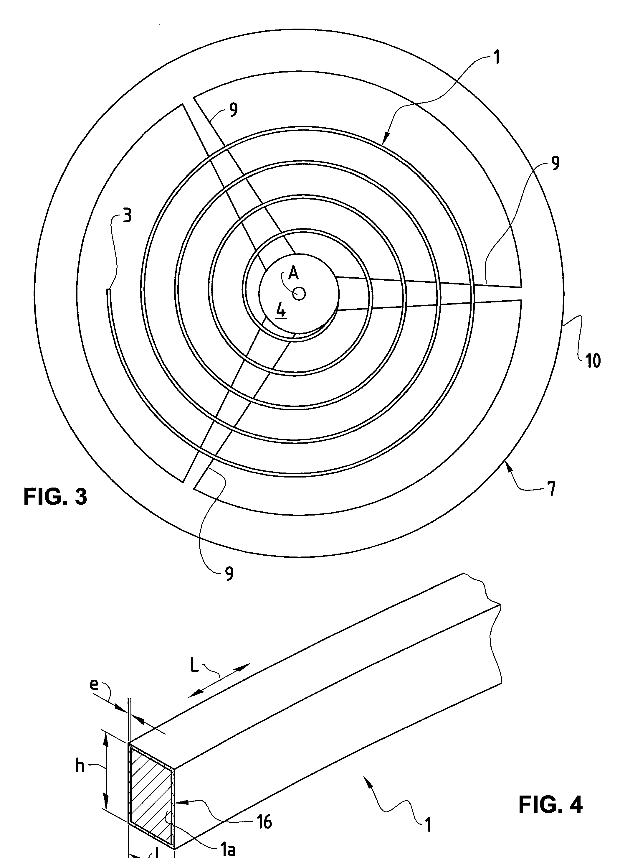
[0037]FIG. 1 represents an example embodiment of a spiral spring 1 which can be used in a mechanical oscillator according to the invention. The spiral spring 1 has a central end 2 and an eccentric end 3. The central end 2 is integral with a rotary collet 4, provided with an orifice intended to receive an arbor of rotation about an axis of rotation A (represented by a broken line). The rotary collet 4 is intended to be mounted on a stationary support (not shown). The rotary collet 4 and the spiral spring 1 can be produced in particular in a ingle piece, without a separate mounting being necessary. It is nevertheless also conceivable for the rotary collet 4 to be formed separately and be fixed to the central end 2 of the spiral spring 1 by means of a known mounting. The eccentric end 3 is intended to be integral with a stationary element called “balance-cock” and not represented in the figures. For this purpose several means of common mountings are possible.

[0038]The mechanical oscill...


PUM


Abstract

The invention relates to a mechanical oscillator, in particular for watchmaking, comprising a spiral spring (1) having a number N of turns, a central end (2), an eccentric end (3) and a rotary collet (4), connected to the central end (2), comprising an orifice intended to receive an arbor for rotation about an axis (A), and a balance (7), the axis of rotation of which coincides with the rotation arbor (A), the eccentric end (3) being intended to be integral with a stationary element of the “balance-cock” type, said spiral spring (1) being made up of a single-crystal silicon (Si) core (1a) and at least one peripheral coating (1b) based on a material having a thermoelastic coefficient different from that of silicon, the single-crystal silicon (Si) being oriented along the crystallographic axis {1,1,1} to optimize the temperature coefficient of the mechanical oscillator as a whole. In addition, this invention likewise relates to a method of designing said mechanical oscillator, consisting in optimizing the temperature coefficient of the complete oscillator in order to limit its thermal drift.

Description

TECHNICAL FIELD OF THE INVENTION[0001]This invention relates to the general technical field of mechanical oscillators, also referred to resonators or spiral balances, used in watchmaking, for example.[0002]The invention concerns more specifically mechanical oscillators comprising a spiral spring and a balance and having a temperature coefficient which is suitable to be best reduced so as to limit the thermal drift of said oscillators which influences in a negative way the precision of the watchmaking piece.[0003]Understood by thermal or thermoelastic coefficient should be the variation in seconds in the daily running of a horological movement for a difference in temperature of 1° C. (or 1° K).BACKGROUND ART[0004]Known by way of the document DE 101 27 733, for example, is to achieve spiral springs having a good resistance to large-scale thermal stresses as well as good stability in shape. These springs are made up of single-crystal silicon along diverse crystallographic axes. A coati...

Claims


Application Information

Patent Timeline
Patent Type & Authority Applications(United States)
IPC IPC(8): G04B17/06G06F17/50
CPCG04B1/145G04B17/066H03H9/02448H03H3/0076G04B17/227
Inventor GYGAX, PIERREGLASSEY, MARC-ANDRE
Owner MFG & FAB DE MONTRES & DE CHRONOMETRES ULYSSE NARDIN LE LOCLE SA
Learn More