
Multi-Layer Piezoelectric Element, and Ejection Apparatus and Fuel Ejection System That Employ the Same

Active Publication Date: 2010-11-18
KYOCERA CORP
View PDF15 Cites 24 Cited by
  • Summary
  • Abstract
  • Description
  • Claims
  • Application Information

AI Technical Summary

Benefits of technology

[0015]In the first multi-layer piezoelectric element of the present invention, the piezoelectric material layer comprises a plurality of piezoelectric crystal grains, while the plurality of metal layers comprise internal electrodes and the low-rigidity metal layer that has rigidity lower than those of the internal electrodes and the piezoelectric material layer, and the low-rigidity metal layer comprises a plurality of metal parts that are separated from each other.
[0021]Also because the second multi-layer piezoelectric element of the present invention comprises the bonding material that bonds the adjacent piezoelectric crystal grains and the metal part, bonding between the piezoelectric crystal grains and the metal part is increased. As a result, position of the metal part can be stabilized and the multi-layer piezoelectric element having stable amount of displacement is obtained.

Problems solved by technology

As a result, the element is subject to intense stresses.

Method used


Image

  • Multi-Layer Piezoelectric Element, and Ejection Apparatus and Fuel Ejection System That Employ the Same
  • Multi-Layer Piezoelectric Element, and Ejection Apparatus and Fuel Ejection System That Employ the Same
  • Multi-Layer Piezoelectric Element, and Ejection Apparatus and Fuel Ejection System That Employ the Same

Examples


first embodiment

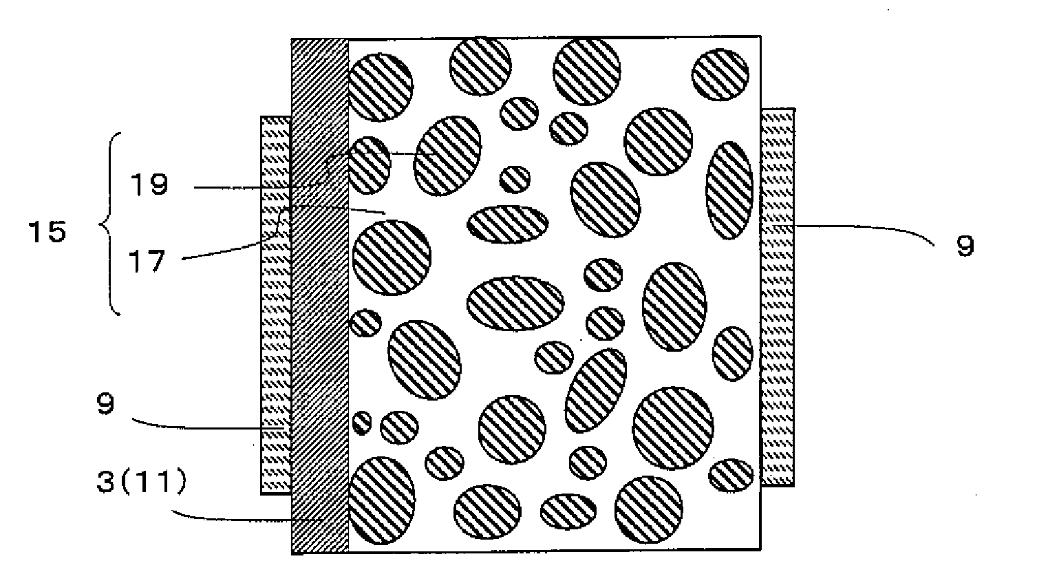
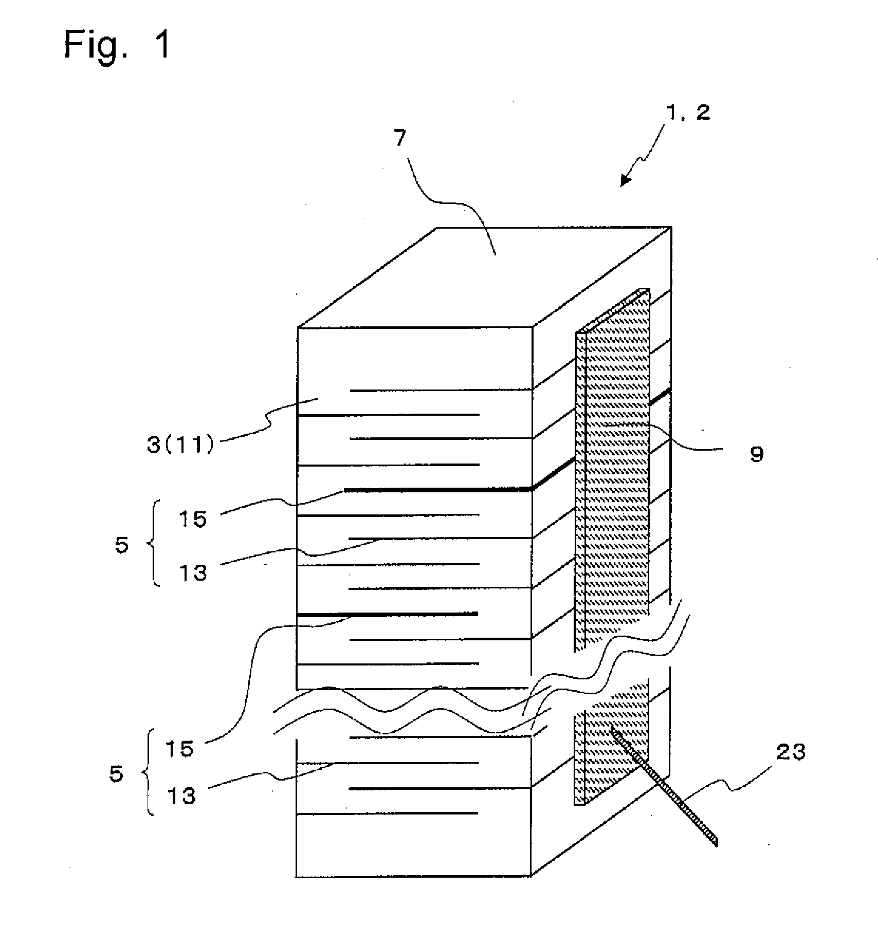
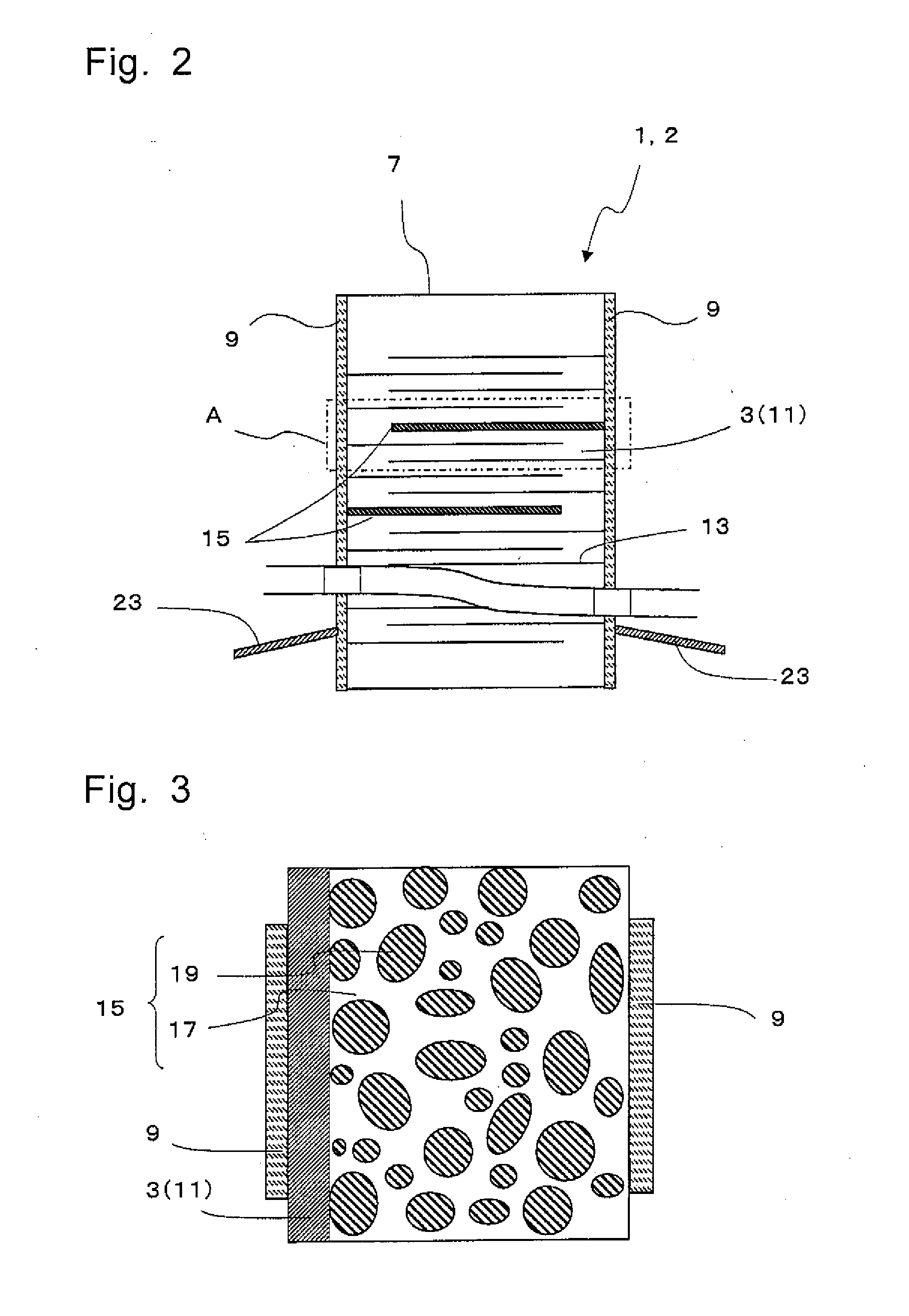
[0058]As shown in FIG. 1 to FIG. 3, the multi-layer piezoelectric element 1 (this may hereafter be referred to also as element 1) of the first embodiment comprises a multi-layer structure 7 in which a plurality of piezoelectric material layer 3 and a plurality of metal layers 5 are stacked alternately one on another and external electrodes 9 formed on the side faces of the multi-layer structure 7. Each of the piezoelectric material layers 3 comprises a plurality of piezoelectric crystal grains 11. The plurality of metal layers 5 comprise internal electrodes 13 that are electrically connected to the external electrode 9 and low-rigidity metal layers 15 that have rigidity lower than those of the internal electrodes 13 and the piezoelectric material layer 3.

[0059]In the first embodiment, the low-rigidity metal layer 15 is a layer of lower rigidity that has weaker bonding strength within the layer and / or between the adjacent layers compared to the piezoelectric material layer 3 and the ...

second embodiment

[0071]The second multi-layer piezoelectric element 2 according to the second embodiment of the present invention will be described in detail below with reference to the accompanying drawings. As shown in FIG. 1 to FIG. 5, the multi-layer piezoelectric element 2 of the second embodiment comprises the multi-layer structure 7 in which a plurality of piezoelectric material layers 3 and a plurality of metal layers 5 are stacked alternately one on another, and the external electrodes 9 formed on the side faces of the multi-layer structure 7, similarly to the first embodiment. The plurality of metal layers 5 comprise the internal electrodes 13 that are electrically connected to, the external electrodes 9 and the low-rigidity metal layers 15 that have rigidity lower than those of the internal electrodes 13 and the piezoelectric material layer 3.

[0072]In the second embodiment, the low-rigidity metal layer 15 is a layer of low rigidity that has weaker bonding strength within the layer and / or ...

examples

[0127]The multi-layer piezoelectric element 1 of the present invention was fabricated as described below.

[0128]First, a stock material powder constituted from lead titanate zirconate (PZT) having mean particle size of 0.4 μm as the main component, a binder and a plasticizer were mixed to form a slurry which was formed into ceramic green sheets A having thickness of about 150 μm by the doctor blade process. Ceramic green sheets B having thickness of about 150 μm were also formed by mixing tetraethoxysilane (TEOS) in slurry so that 0.01 wt % of SiO2 was contained in the PZT powder as the bonding material 21.

[0129]Then an electrically conductive paste A was prepared by adding a binder to a stock material powder that contained a silver alloy powder of composition Ag 95 wt %-Pd 5 wt %. An electrically conductive paste B was also prepared by adding a binder to a stock material powder that contained a silver alloy powder of composition Ag 98 wt %-Pd 2 wt %. In addition, an electrically con...


PUM


Abstract

A multi-layer piezoelectric element having high durability of which amount of displacement is suppressed from varying even when operated continuously over a long period of time with a higher electric field under a high pressure is provided.The multi-layer piezoelectric element which has a multi-layer structure, the multi-layer structure comprising a plurality of piezoelectric material layers and a plurality of metal layers that are stacked alternately, wherein the piezoelectric material layer is constituted from a plurality of piezoelectric crystal grains, the plurality of metal layers comprise internal electrodes and low-rigidity metal layer that has rigidity lower than those of the internal electrodes and the piezoelectric material layer, and wherein the low-rigidity metal layer has a plurality of metal parts that are separated from each other, and an end of the metal part infiltrates between the piezoelectric crystal grains.

Description

TECHNICAL FIELD[0001]The present invention relates to a multi-layer piezoelectric element, an ejection apparatus and a fuel ejection system, for example a multi-layer piezoelectric element used as the drive element (piezoelectric actuator) for fuel ejection apparatus of automobile engine, liquid ejection apparatus of ink jet printer or the like, precision positioning device or vibration preventing device for an optical apparatus, as a sensor element used in combustion pressure sensor, knocking sensor, acceleration sensor, load sensor, ultrasonic sensor, pressure sensor, yaw rate sensor or the like, or as a circuit component mounted in piezoelectric gyro, piezoelectric switch, piezoelectric transducer, piezoelectric breaker or the like, and an ejection apparatus and a fuel ejection system that employ the multi-layer piezoelectric element.BACKGROUND[0002]There have been demands for a greater amount of displacement as well as size reduction of the multi-layer piezoelectric element. As ...

Claims


Application Information

Patent Timeline
IPC IPC(8): B05B1/08H01L41/04H01L41/273
CPCF02M51/0603H01L41/273H01L41/0838H10N30/508H10N30/053
Inventor OKAMURA, TAKESHI
Owner KYOCERA CORP
Learn More