
Pneumatic Tire

a technology of pneumatic tires and air columnar resonance, which is applied in the direction of non-skid devices, vehicle components, transportation and packaging, etc., can solve the problems of air columnar resonance noise generation, and achieve the effects of reducing air columnar resonance noise, improving friction resistance against air flow in the main groove, and improving dry steering stability

Inactive Publication Date: 2010-11-18
TOYO TIRE & RUBBER CO LTD
View PDF6 Cites 4 Cited by
  • Summary
  • Abstract
  • Description
  • Claims
  • Application Information

AI Technical Summary

Benefits of technology

The present invention relates to a pneumatic tire with improved steering stability without raising the level of air columnar resonance noise. The invention is achieved by adding thin grooves in the sidewall of the main groove of the tire. These thin grooves provide friction resistance against the air flow in the main groove, reducing air columnar resonance noise. The thin grooves are formed at intervals along the tire circumferential direction and are designed to ensure dry steering stability in the early wear of the tire. The invention helps to improve the steering stability of the tire without compromising its rigidity and drainage performance.

Problems solved by technology

The rotation of tires lets air compressed in the tubular space to release outside, and as a result, air columnar resonance noise is generated.

Method used


Image

  • Pneumatic Tire
  • Pneumatic Tire
  • Pneumatic Tire

Examples


example

[0031]Tires of Example according to the present invention and Comparative examples were manufactured and evaluated, respectively. Evaluation was made on the tire which has a size of 195 / 65R15 and a tread pattern comprising five rows of blocks of square shape whose one side is 30 mm formed by main grooves and transverse grooves each having 10 mm in width, and which is mounted to the rim having a rim size of 15×6J.

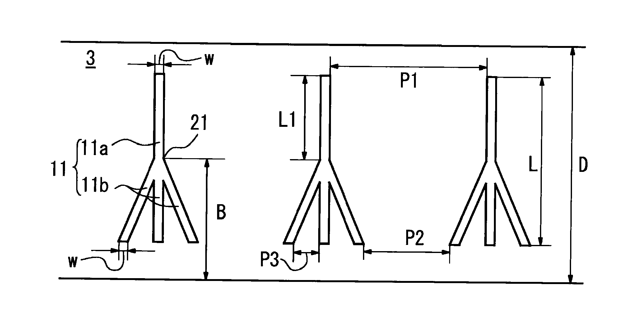
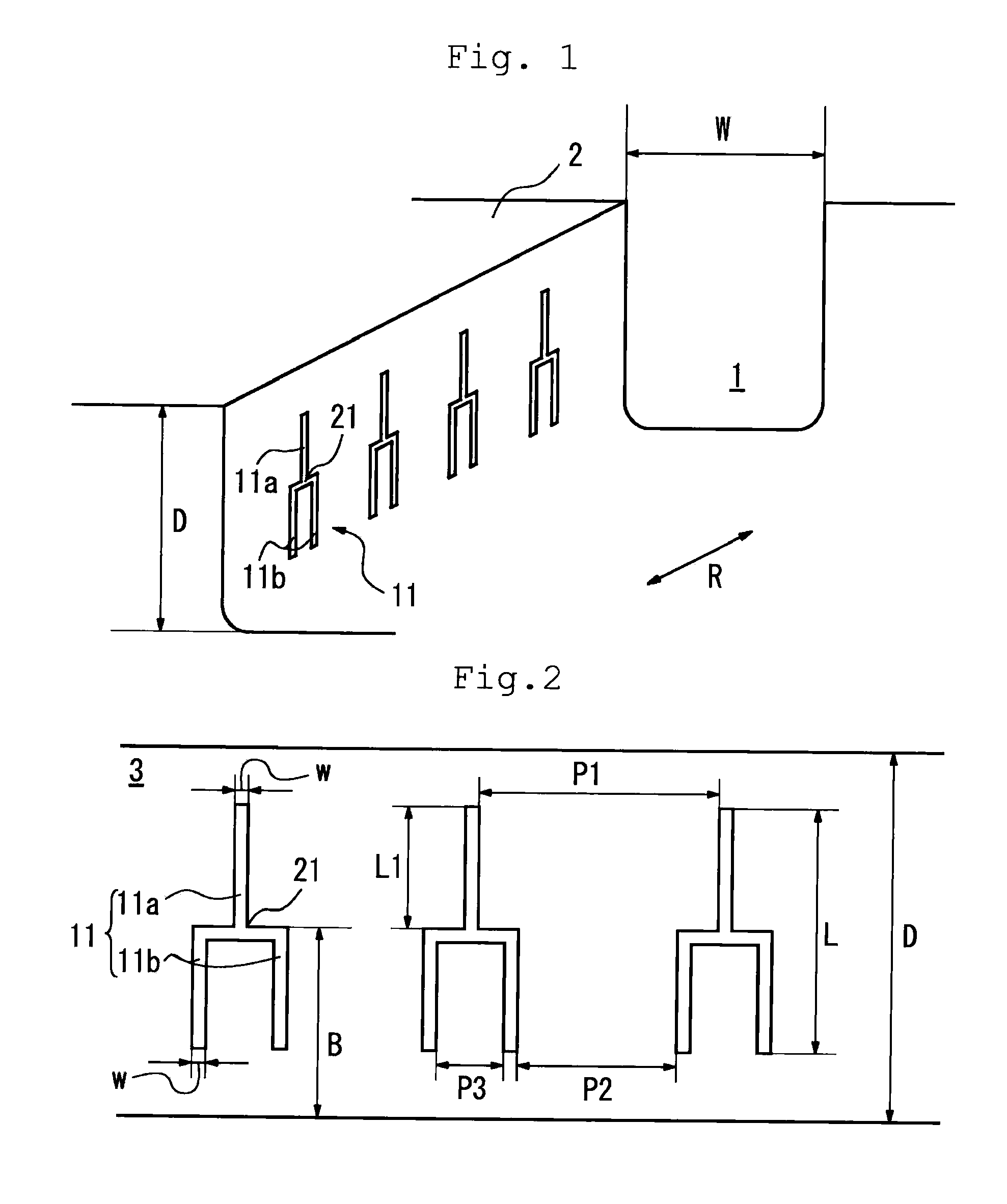
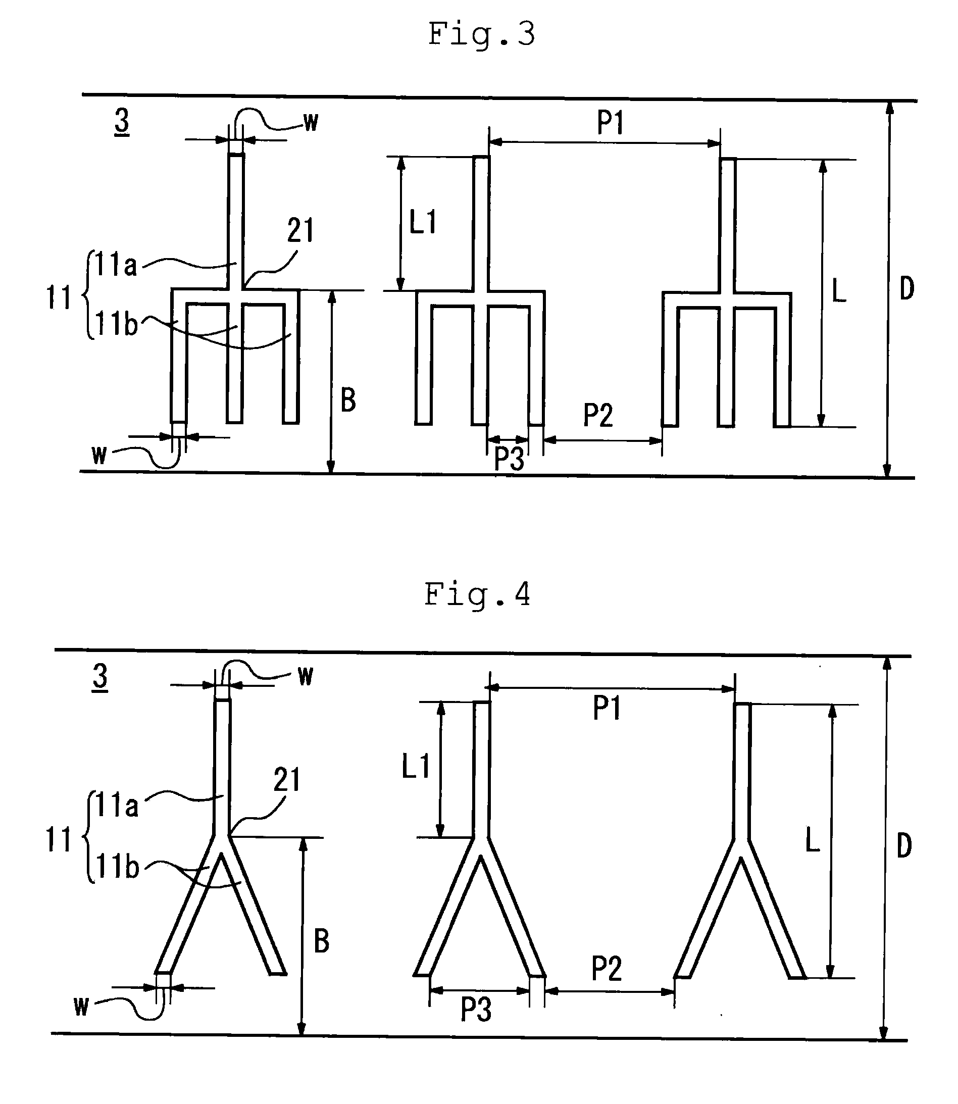
[0032]The tires comprising thin grooves as shown in FIGS. 1 and 2 were used in Examples. The tire of Comparative example 1 was provided with unbranched thin grooves (whose width w is 0.5 mm, depth d is 0.5 mm, length L is 6.0 mm and space is 1.1 mm) extending in the depth direction of the main groove 1. In Comparative example 2, the tire comprising upper thin grooves and lower thin grooves having the same dimension as Examples and which are not joined together was used. Each dimension of the thin grooves was as shown in Table 1.

[0033]Evaluation results are shown in FIG. 1. D...


PUM


Abstract

A pneumatic tire with improved steering stability without raising air columnar resonance noise level is provided. The pneumatic tire comprises upper thin grooves 11a extending from a branch point 21 in the depth direction of a main groove on the tread surface side and a plurality of lower thin grooves 11b extending from the branch point 21 in the depth direction of the main groove on the groove bottom side, which are formed at intervals along the tire circumferential direction R in a sidewall of the main groove and a distance B from the groove bottom of the main groove 1 to the branch point 21 is 30 to 60% of the depth D of the main groove 1.

Description

TECHNICAL FIELD[0001]The present invention relates to a pneumatic tire with improved steering stability without raising air columnar resonance noise level.[0002]This application claims benefit of priority based on Japanese Patent Application No. 2007-257675 filed on Oct. 1, 2007, the entire same contents of which are incorporated by reference herein.BACKGROUND ART[0003]In a state where a tire contacts the ground, tubular space is formed by a main groove extending in the tire circumferential direction and road surface. The rotation of tires lets air compressed in the tubular space to release outside, and as a result, air columnar resonance noise is generated. Since the air columnar resonance noise is offensive noise whose frequency is around 1 kHz, reduction in air columnar resonance noise has been demanded conventionally. For example, the pneumatic tire disclosed in the patent document 1 has a great number of oblong holes extending in the depth direction of a main groove formed in a...

Claims


Application Information

Patent Timeline
Patent Type & Authority Applications(United States)
IPC IPC(8): B60C11/03
CPCB60C11/0309B60C2011/133B60C11/13
Inventor OHASHI, TOSHIYUKI
Owner TOYO TIRE & RUBBER CO LTD
Learn More