Localized sealant application in aerostats

a sealant and aerostat technology, applied in the field of aerostats, can solve the problems of adversely affecting the lifting capacity, etc., and achieve the effects of reducing the overall weight of the aerostat, limiting the physical size of the aerostat, and cost saving

Inactive Publication Date: 2010-11-18
ANAGRAM INT INC
View PDF18 Cites 6 Cited by
  • Summary
  • Abstract
  • Description
  • Claims
  • Application Information

AI Technical Summary

Benefits of technology

[0007]The conventional practice of employing heat sealing layers on aerostats results in undesirable weight that can adversely impact the lifting capacity and ultimately limit the physical size of the aerostat. The present invention applies an adhesive onto one or more barrier films at the desired point of bonding between the films. This practice eliminates the need to utilize a heat sealant layer across the entirety of the film—a cost savings. The reduction of overall weight of the aerostat results in a corresponding increase in lifting capacity necessary for the aerostat to maintain aloft.
[0009]Additionally, the use an adhesive at the desired point of bonding enables the formation of aerostats with dimensionally smaller structures than those enabled by previous constructions. This is primarily due to the reduction in mass due to the elimination of a sealant layer. At least one embodiment permits the formation of an aerostat having an internal volume of greater than about 2000 cm3. That volume is significantly lower than those that are limited through the production of heat sealant layers.

Problems solved by technology

The conventional practice of employing heat sealing layers on aerostats results in undesirable weight that can adversely impact the lifting capacity and ultimately limit the physical size of the aerostat.

Method used


Image

  • Localized sealant application in aerostats
  • Localized sealant application in aerostats

Examples


Embodiment Construction

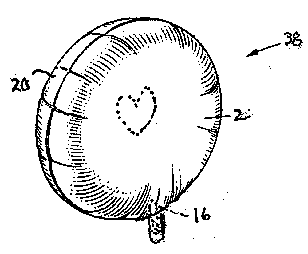
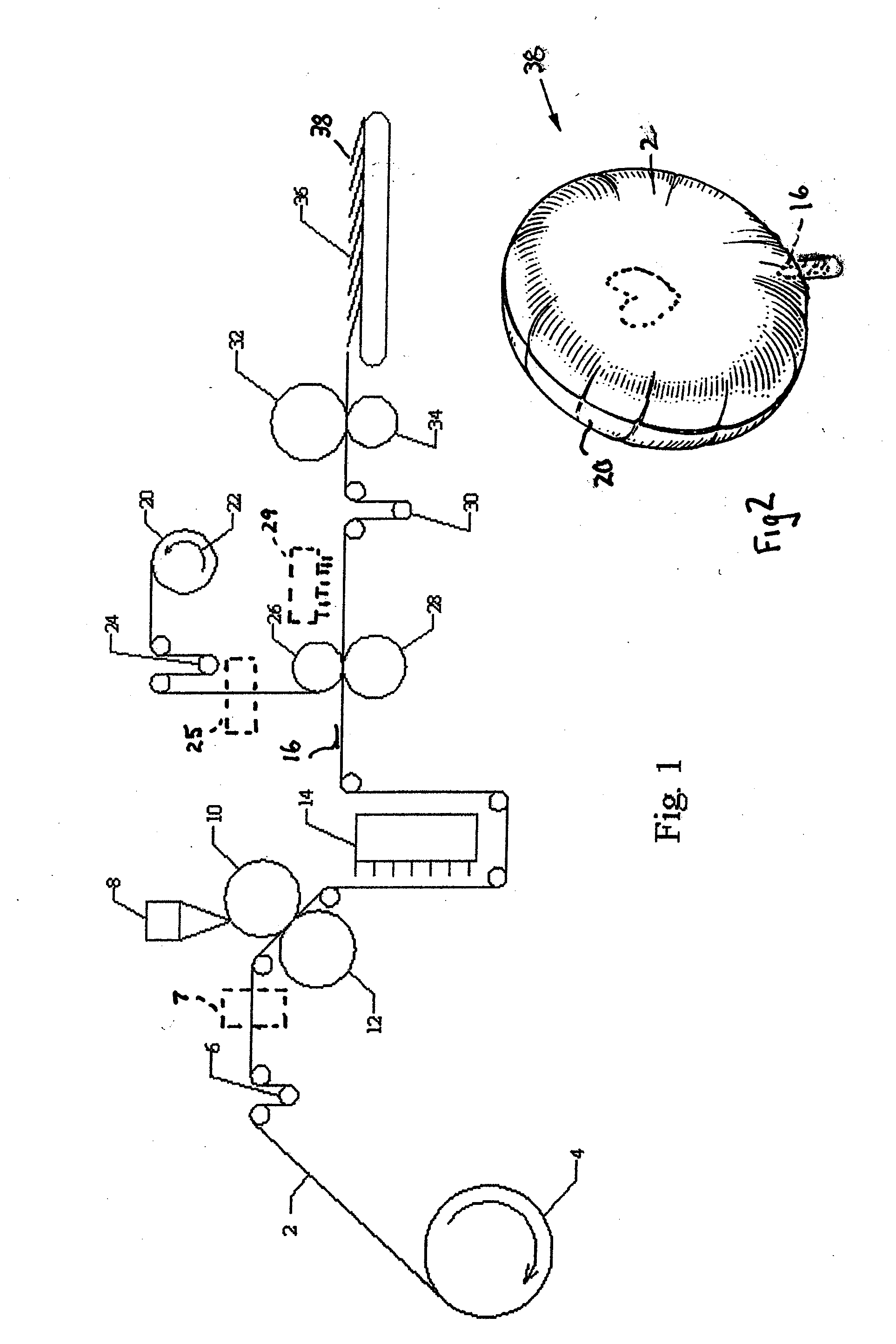
[0014]The present invention applies an adhesive onto one or more barrier films at the desired point of bonding between the films. The method of applying an adhesive at the desired point of bonding can be accomplished by coating techniques such as flexographic printing, inkjet printing, roll transfer, or silk screening techniques. The adhesive is applied about the periphery in some applications after the printing of desired art or graphics and just prior to the point of bonding the two barrier films together. The method of the present invention results in aerostats with a bond line at the edge of the desired shape. The reduced weight, in comparison to conventional practices employing a heat sealing layer, enables intricate designs and smaller volume aerostats.

[0015]Those of ordinary skill in the art of manufacturing aerostats, such as novelty balloons, recognize that barrier films are necessary to prevent the depletion of the lighter than air gas from the balloon. For purposes of the...


PUM

PropertyMeasurementUnit
Linear densityaaaaaaaaaa
Volumeaaaaaaaaaa
Weightaaaaaaaaaa

Abstract

Formation of an aerostat through the application of a pressure sensitive adhesive onto one or more barrier films at the desired point of bonding between the films. The adhesive is applied about the periphery prior to the point of bonding the two barrier films together. The method of the present invention results in aerostats with a bond line at the edge of the desired shape. The reduced weight, in comparison to conventional practices employing a heat sealing layer, enables intricate designs and smaller volume aerostats.

Description

CROSS-REFERENCE TO RELATED APPLICATION[0001]This application claims priority from U.S. Provisional Patent Application Ser. No. 61 / 179,124 filed on May 18, 2009 entitled Localized Sealant Application in Aerostats.TECHNICAL FIELD[0002]The present invention relates to an aerostat utilizing a differentiated bonding mechanism to enclose lighter than air gases between two or more barrier films.BACKGROUND OF THE INVENTION[0003]Aerostats are objects using principles of aerostatics to float, i.e. lighter than air objects, such as balloons, that derive their lift from the buoyancy of surrounding air rather than from aerodynamic motion. According to Archimedes Principle, an object is buoyed up by a force equal to the weight of the fluid displaced by the object. For an aerostat, the buoyant force must be sufficient enough to overcome the total weight of the aerostat in order to float.[0004]Aerostats generally consist of a relatively thin film material creating a volumetric body that contains a ...

Claims


Application Information

Patent Timeline
IPC IPC(8): G09F21/06B32B38/04
CPCA63H27/10Y10T156/1074B29C65/1406B29C65/4845B29C65/526B29C65/8207B29C66/7352B29C66/83413B29C2035/0827B29C2793/009B29C2795/002B29K2023/00B29K2029/00B29K2067/043B29K2067/046B29K2077/00B29K2305/00B29K2309/02B29K2995/0025B29K2995/003B29K2995/0039B29K2995/0053B29K2995/0056B29L2009/00B29L2009/003B29L2022/022G09F21/08B29C65/8215B29C65/4865B29C65/4825A63H2027/1025B29C66/73921B29C66/73772B29C66/73791B29C66/43B29C66/53262B29C66/71B29C66/72341B29C66/133B29K2067/00B29K2023/06
Inventor BORCHARDT, DEAN SCOTTSWANSON, ANDREW THOMASSARNSTROM, SR., TODD RICHARDCERNOHOUS, JEFFREY JACOBVAN GORDEN, GARRETT SCOTT
Owner ANAGRAM INT INC
Why Eureka
Try Eureka