
Heat exchanger for bathing shower

a technology for heat exchangers and bathing showers, applied in indirect heat exchangers, light and heating apparatuses, laminated elements, etc., to achieve the effects of improving heat exchange efficiency, increasing energy saving effect, and simplifying structure and supporting strength

Inactive Publication Date: 2010-11-11
CAI YING LIN +1
View PDF15 Cites 1 Cited by
  • Summary
  • Abstract
  • Description
  • Claims
  • Application Information

AI Technical Summary

Benefits of technology

"The present invention is a heat exchanger for bathing showers that has a simplified structure and is strong enough to support the weight of the human body. It has internal circulation directing means that improve heat exchanging efficiency, resulting in energy savings and a reduction in manufacturing costs. The heat exchanger is affordable, easy to install, and has a long service life span. It promotes energy savings and reduces carbon footprint, making it more popular and environmentally friendly."

Problems solved by technology

However, some drawbacks still exist in the China Utility Model Patent No.
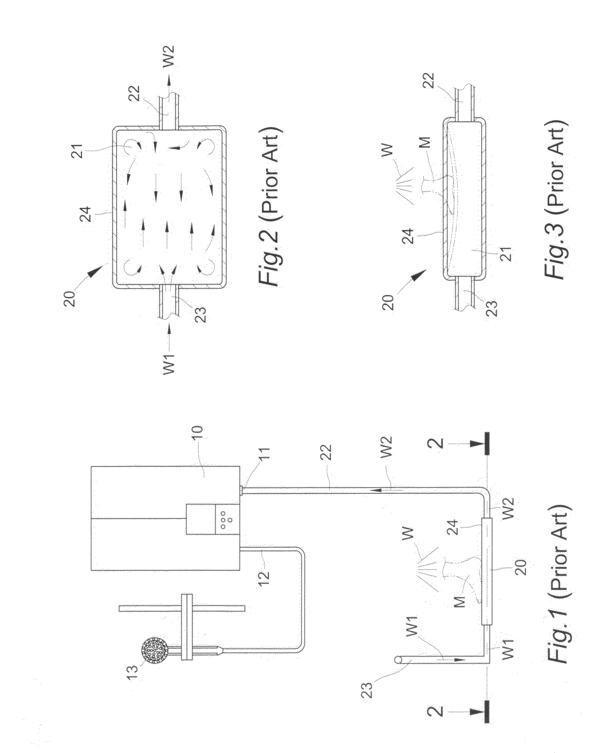
1. Please refer to FIGS. 1 through 3 for metal heat absorbing slab 20. In order to keep the hot shower water W drop on the top surface 24 of the metal heat absorbing slab 20, the shower user M must stand on the top surface 24 of the metal heat absorbing slab 20 so that the metal top surface 24 with hollow chamber 21 beneath will be indented deformation owing to body weight strain of the shower user M for long term use (as hypothetical line shown in FIG. 3). Because metal heat absorbing slab 20 is fabricated by metal welding process, water leakage is incurred from certain metal welding seams on the metal heat absorbing slab 20 being fractured due to indented deformation thereon so that not only the heat exchanging effect will be lost but also certain fractured metal welding seams may cause accidental hurt to the shower user M inadvertently. Moreover, because no circulation directing means is designed in the hollow chamber 21, water turbulences will happen in the chamber 21 after cold tap water W1 flows into therein via the water inlet pipe 23 (as indicting arrow heads shown in FIG. 3) so that the energy saving effect will be considerably decreased in consequence of lowering heat exchanging efficiency.
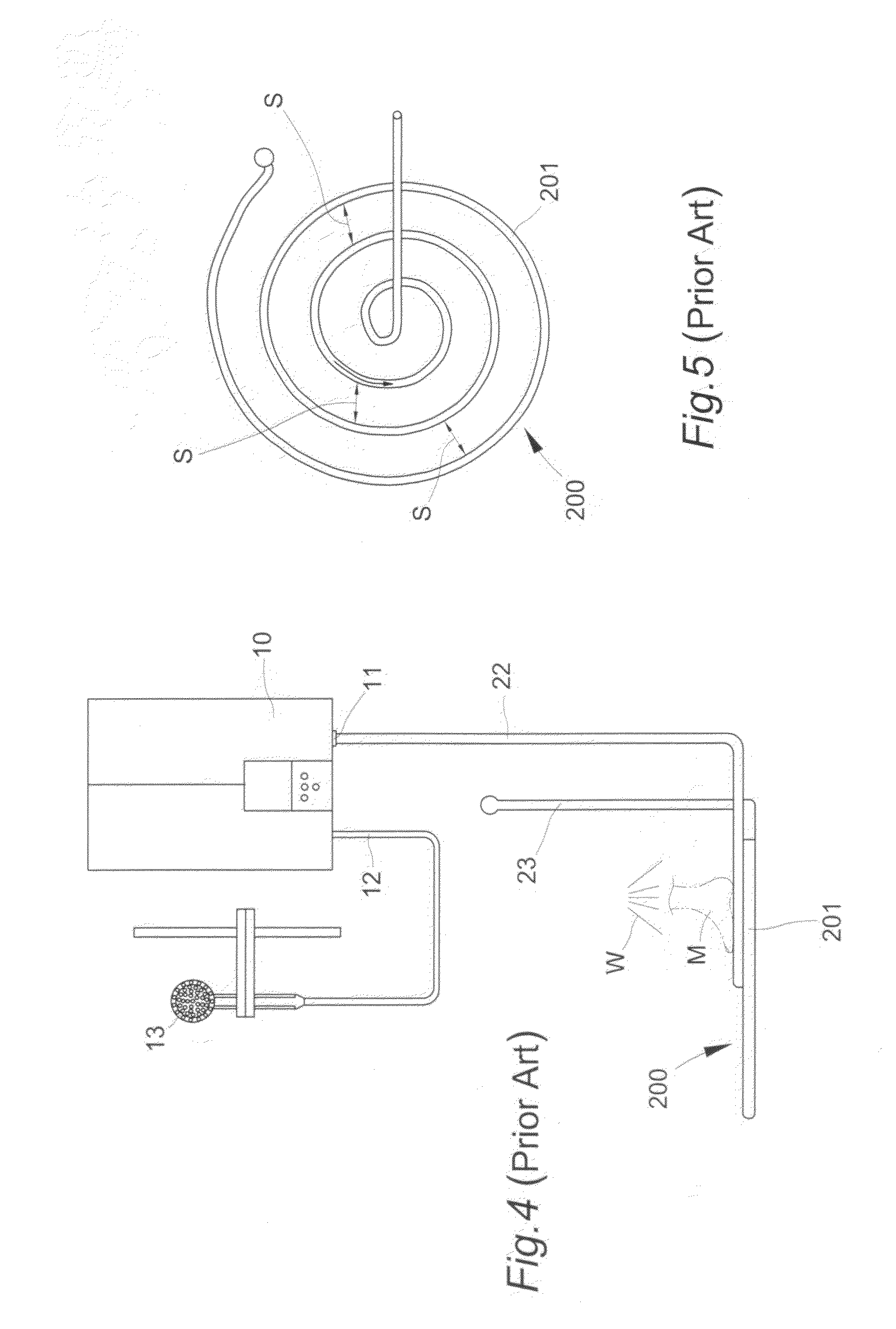
2. Please refer to FIGS. 4 and 5 for metal heat absorbing slab 200. Likewise, in order to keep the hot shower water W drop on the top surface of the metal heat absorbing slab 200, the shower user M must stand on the top surface of the metal heat absorbing slab 200. Because metal heat absorbing slab 200 is formed by spiral metal tube 201 having multiple continual coils with a gap S for each pair of adjacent coils, the round top surface thereof becomes slippery once hot shower water W drops thereon so that the shower user M stands thereon often suffered from injure inadvertently incurred by falling down due to such round slippery surface (as shown in FIG. 4). That is a menace to the safety of the shower user M. Moreover, all the gaps S between each pair of adjacent coils in the spiral metal tube 201 cause no heat exchanging function as the hot shower water W passes therein without contacting to the spiral metal tube 201 (as shown in FIG. 5) so that the energy saving effect will be considerably decreased in consequence of lowering heat exchanging efficiency.
3. The key process for the manufacturing of metal heat absorbing slab 20 in FIG. 1 and metal heat absorbing slab 200 in FIG. 4 is metal welding process, which cause relative high labor cost in manufacturing expense as metal welding process is often worked by high-skilled technician with high salary to maintain high yield. Moreover, the multiple continual coils with a gap S for each pair of adjacent coils for fabricating the spiral metal tube 201 must processed by a tube-bending machine of high accuracy together with metal welding process for welding connection with water inlet pipe 23 and water outlet pipe 22 respectively so that overall manufacturing cost keep soaring high without possibility of lowering down. Thus, the ex-factory price and retail price for the product of metal heat absorbing slab 20 and 200 become particular high with difficulty for lowering down so that not only the purchasing intention of the consumer is retarded but also the product itself becomes unpopular. Therefore, how to contrive an improved product of heat exchanger for bathing shower with simplified structure and relative low manufacturing cost to satisfy with the purchasing ability and intention of customers seem very critical.

Method used


Image

  • Heat exchanger for bathing shower
  • Heat exchanger for bathing shower
  • Heat exchanger for bathing shower

Examples


Embodiment Construction

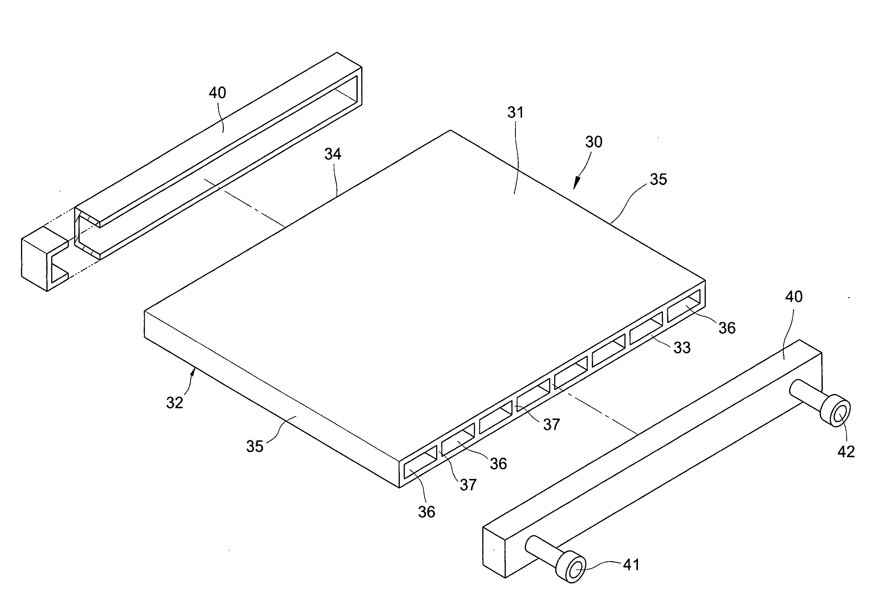
[0026]FIG. 6 through FIG. 8, a “heat exchanger for bathing shower” of the present invention includes a heat exchanging slab 30 and two sealing covers 40 such that one of the sealing covers 40 is created with a water intake 41 and a water outtake 42, wherein:

[0027]The heat exchanging slab 30, which is a flat planar cuboid extruded by alloy metal material, includes a flat top surface 31, a flat bottom surface 32, a front hatch 33, a rear hatch 34, two parallel upright flanks 35, a plurality of parallel water passages 36 penetrated through between the front hatch 33 and rear hatch 34 such that each pair adjacent water passages 36 is partitioned by a septum 37 with a circulating bore 38 created thereon in interlaced stagger manner, which means a bore in upper section of one septum and another bore in lower section of the other septum for each pair of adjacent septa 37 (as shown in FIG. 7); and

[0028]each of two sealing covers 40 respectively covers on the front hatch 33 and rear hatch 34...


PUM


Abstract

The present invention provides a heat exchanger for bathing shower comprising a heat exchanging slab and two sealing covers. The heat exchanging slab is extruded by alloy metal material into simple overall structure to reduce processing steps, total manufacturing cost and selling price. A close water circulation entirety with circulation directing means is created therein to improve heat exchanging efficiency and energy saving effect of the water heater. Thereby, purchasing intention of consumers is increased in consequence of satisfaction of the purchasing ability. Thus, not only the speed and range of the promotion is benefited, but also the environmental protection in energy saving and carbon reducing effect is expedited.

Description

FIELD OF THE PRESENT INVENTION[0001]The present invention relates to an energy saving heat exchanger for a bathing shower, the heat exchanger having a simple structure that significantly decreases manufacturing time and costs and provides enhanced energy saving efficiency so as to make the heat exchanger more affordable and attractive to consumers. Thus, the invention not only provides increased popularity but also offers environmental protection due to increased energy saving and reduced carbon emissions.BACKGROUND OF THE INVENTION[0002]For the purpose of reducing their carbon footprint, many heat exchangers for bathing showers used in households have been introduced in the market. The design concept is that incoming cold tap water running through the heat exchanger is heated up by hot waste water from the shower, which serves as a thermal source, so that the temperature of the tap water output from the heat exchanger becomes warmer than that of the incoming tap water, the output b...

Claims


Application Information

Patent Timeline
Patent Type & Authority Applications(United States)
IPC IPC(8): F28F1/00
CPCF28D9/0081F28D21/0012F28D1/0246F28F2250/04Y02B30/566F28F3/12Y02B30/56
Inventor CAI, YING LIN
Owner CAI YING LIN
Learn More