
Optically Clear Biofouling Resistant Compositions and Methods for Marine Instruments

a composition and composition technology, applied in the field of marine instruments, can solve the problems of affecting the data acquisition, affecting the performance of marine instruments and sensors, and affecting the maintenance cost of instruments, and achieves excellent long-term biofouling resistance properties, good adhesion to the substrate, and coating durability

Active Publication Date: 2010-11-04
SEVERN MARINE TECH +1
View PDF22 Cites 38 Cited by
  • Summary
  • Abstract
  • Description
  • Claims
  • Application Information

AI Technical Summary

Benefits of technology

[0023]The present invention also provides a method of coating marine instruments comprising housing and sensor elements, said method capable of forming an optically clear biofouling resistant coating having excellent biofouling resistant properties, a high degree of coating adhesion to the substrate as well as a high degree of coating durability.
[0032]The present invention also provides an optically clear biofouling resistant coating composition and method for marine instruments comprising housing and sensor elements, said composition capable of forming a coating having excellent long term biofouling resistant properties, coating durability and good adhesion to the substrate, said method and composition being environmentally friendly and safe to handle.

Problems solved by technology

These plants and animals cause various types of damages, and particularly adhere to and degrade the performance of marine instruments and sensors.
The biofouling of marine and other aquatic instrumentation is a long-felt and well-established problem by those in industry, science and resource management, as biofouling inhibits the performance of marine instrumentation, thereby adversely affecting the data acquired as well as adding to the cost of maintaining the instruments.
Problems due to biofouling of marine instrumentation have been occurring for many decades and continue to be a major factor inhibiting the effective use of submerged instruments.
Biofouling on the marine instrument housing causes messy handling of the instrument upon retrieval; increases the surface area of the housing thereby making the instrument more susceptible to forces imparted on it from current, waves or other moving water; increases the weight of the instrument both in and out of the water; increases personnel time to clean with an associated increase in operation and maintenance cost the biofouling that attaches to the surface area of the housing has a tendency to migrate towards the sensor area.
Additionally, the biofouling on the sensor elements can attenuate sensor signals, disrupt critical spacing between conductor elements, disable optical devices due to blockage of light transmission through their elements; block open ports of pressure or sensing chambers, clogs open flow cylinders of some sensors and some biofouling organisms such as barnacles can bore into the transducer elements, thereby damaging them.
Biofouling of marine instruments comprising a housing and sensor element continues to be a persistent problem.
Prior art techniques have obvious limitations.
Furthermore, greases may have adverse environmental effects as they are in some cases toxic to non-biofouling marine life and to workers handling and maintaining the marine instruments.
On the other hand, paints or any opaque coating will not work on optical sensors as they will disrupt light transmission in the same manner that biofouling itself does.
Additionally, metal biocide released from various paints or greases cannot work with electrode or electromagnetic sensor elements as they will disrupt the generated signal.
Fouling does however occur and the mechanical systems use a significant amount of battery power for those devices that are battery powered.
Furthermore, paints containing active biocides or other biocide applications lose their efficacy over time.
Where marine instruments have been coated with opaque biofouling resistant material, the coating occludes the identity of the instrument causing manufacturers to loose their identifying look and branding; serial numbers and other identification markings.
US 20080255304 relate to integrally molded body of silicone resin and silicone rubber but does not teach an antibiofouling composition.
Prior art does not provide optically clear silicones nor address the issue of poor silicone adhesion to a wide variety of marine instrument surfaces, particularly adhesion promotion in a manner that does not interfere with light transmission.

Method used


Image

  • Optically Clear Biofouling Resistant Compositions and Methods for Marine Instruments
  • Optically Clear Biofouling Resistant Compositions and Methods for Marine Instruments
  • Optically Clear Biofouling Resistant Compositions and Methods for Marine Instruments

Examples


example 1

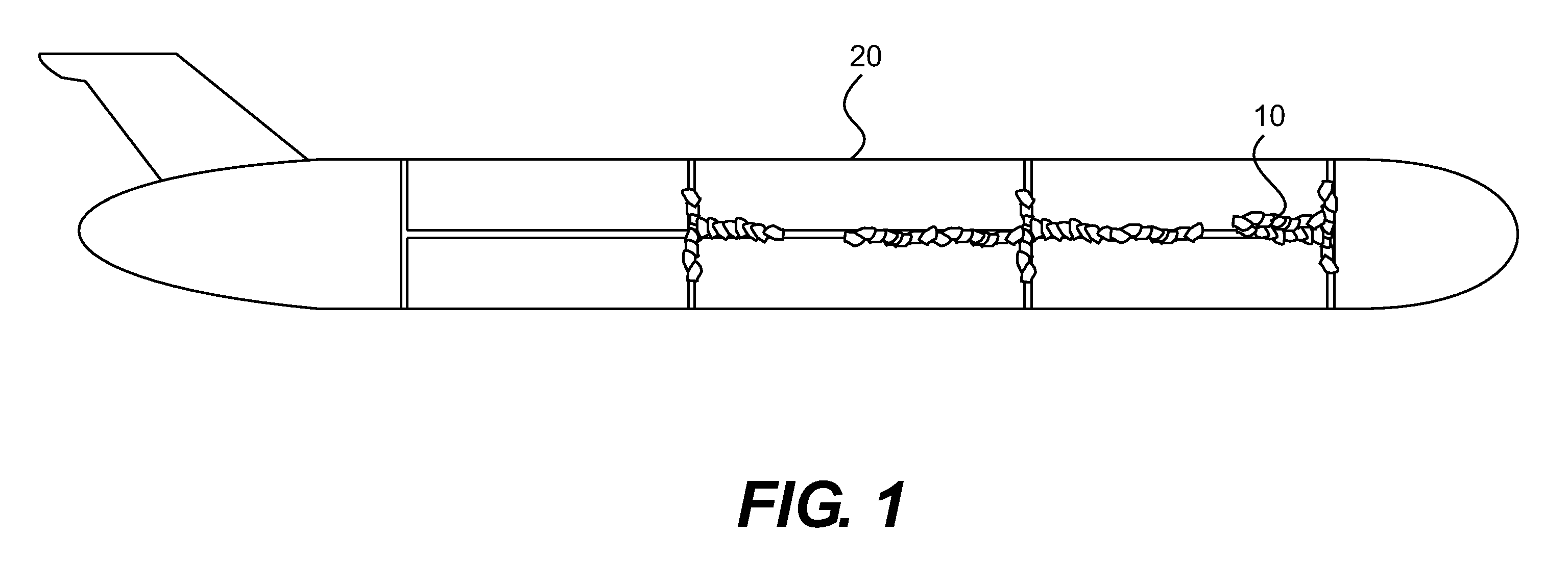
[0091]For the case of instrument housings, gliders and similar platforms, special care is taken to coat the areas where sections of housing are joined together with o-ring connections or have installed end caps with o-ring sections. FIG. 1 illustrates biofouling in o-ring jointed seams 10 of multi-component instrument housing 20. In order to protect these areas from biofouling settlement and to ensure that the applied fouling release coating does not flow into the o-ring sealed area where it could disrupt the sealing mechanism, the following method of coating is implemented. A layer of clear plastic tape is applied to cover the o-ring bearing seams joining two pieces of the instrument housing. To equalize the pressure across the tape, a hole or holes is made on the tape. The anti-fouling coating is then applied over the tape in accordance with the teachings of the present invention. The circular circumference, joining two pieces of the instrument housing as described have a layer of...


PUM

PropertyMeasurementUnit
Fractionaaaaaaaaaa
Fractionaaaaaaaaaa
Fractionaaaaaaaaaa

Abstract

An optically clear biofouling resistant coating compositions specially formulated for very high light transmission and more particularly coating compositions which can be applied to marine instruments and sensors. The compositions provide a biofouling resistant coating on the surface of the marine instruments and sensors which prevents underwater organisms from adhering and growing on the surfaces of the structures over a long period of time.

Description

[0001]This invention claims priority to U.S. Provisional Patent Application No. 61 / 155,860 filed Feb. 26, 2009.BACKGROUND OF THE INVENTION[0002]1. Field of the Invention[0003]The present invention relates to optically clear biofouling resistant coating organosiloxane compositions specially formulated for very high light transmission, and more particularly to coating compositions which can be applied to marine instruments and sensors. The compositions provide a biofouling resistant coating on the surface of the marine instruments and sensors which prevents underwater organisms from adhering and growing on the surfaces of the structures over a long period of time.[0004]2. Description of the Prior Art[0005]A large number of organisms such as barnacles, bacterial slimes, ascidians, serupulas, fresh- and salt-water mussels, polyzoan, green algae, sea lettuce and the like live in the waters of the sea, rivers, lakes and swamps. These plants and animals cause various types of damages, and ...

Claims


Application Information

Patent Timeline
IPC IPC(8): A01N55/10A01P13/00A01P1/00A01P15/00A01P17/00B05D1/36B05D3/00
CPCA01N55/00C08L75/04C09D5/1675C09D5/14C09D5/1625C09D5/1693C09D183/04
Inventor LOBE, HENRYKNAPP, JOHNDAS, AMULYA K.MOFFAT, GARY
Owner SEVERN MARINE TECH
Learn More