
System and method implementing short-pulse propagation technique on production-level boards with incremental accuracy and productivity levels

a technology of production-level boards and propagation techniques, applied in the field of systems and techniques for modeling and characterizing printed circuit board wiring, can solve the problems of limited techniques for providing time and frequency domain measurements, inaccurate signal integrity and timing prediction, and simulator convergence problems, and achieve the effect of fast testing

Inactive Publication Date: 2010-11-04
GLOBALFOUNDRIES INC
View PDF7 Cites 25 Cited by
  • Summary
  • Abstract
  • Description
  • Claims
  • Application Information

AI Technical Summary

Benefits of technology

[0033]during the testing, coupling the RF connector devices to a surface test pad connector that minimizes a length of the stub portion.
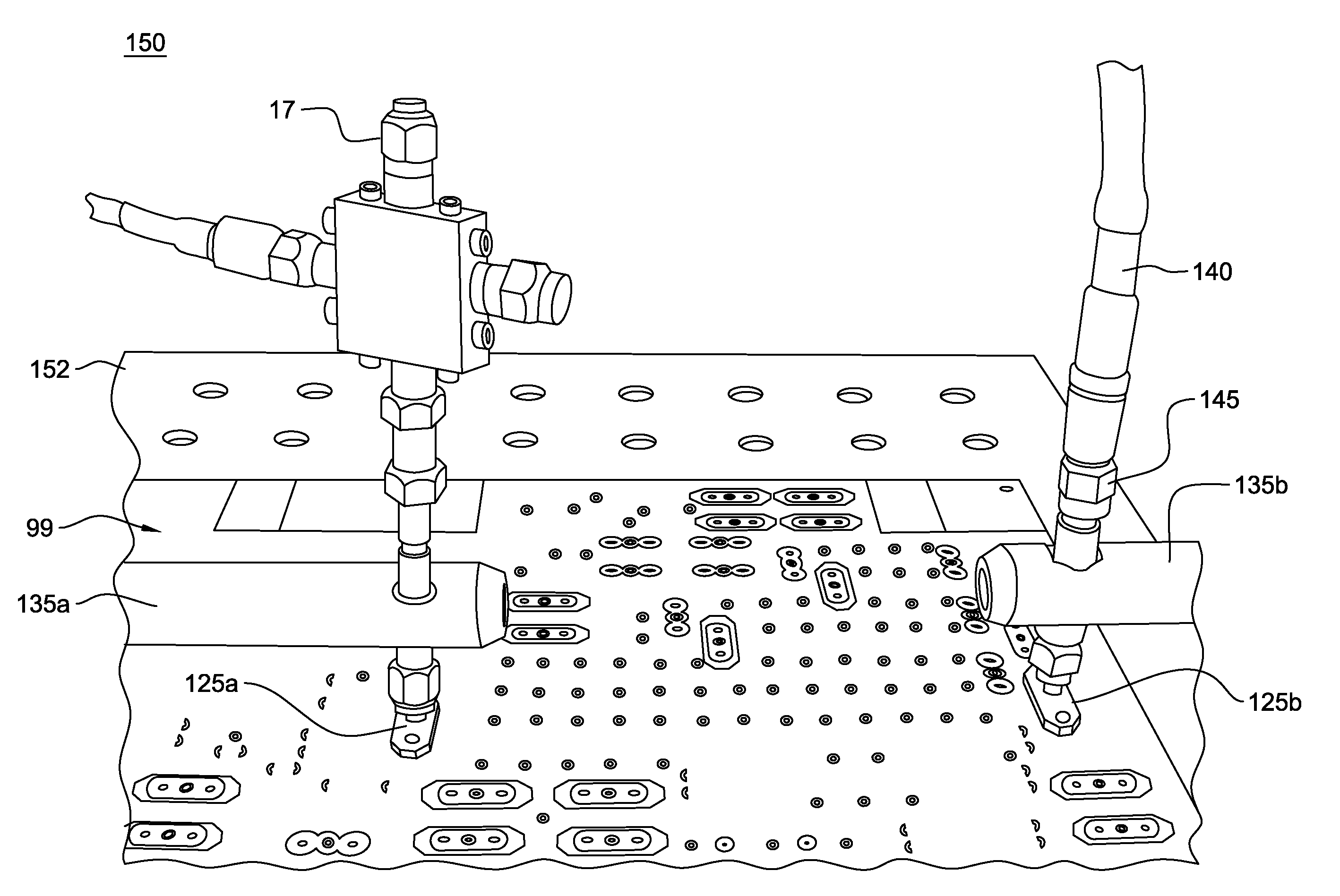
[0049]Advantageously, the system and method of the present invention enables testing of PCBs in a production level environment. In such environments, very thick boards are tested with very long plated through-hole (PTH) vias. Testing may be performed on many boards within short time by operators who are not familiar with advanced, delicate measurement technique. The set-up is automated or semi-automated for large volume, fast testing and robust for rough handling.

Problems solved by technology

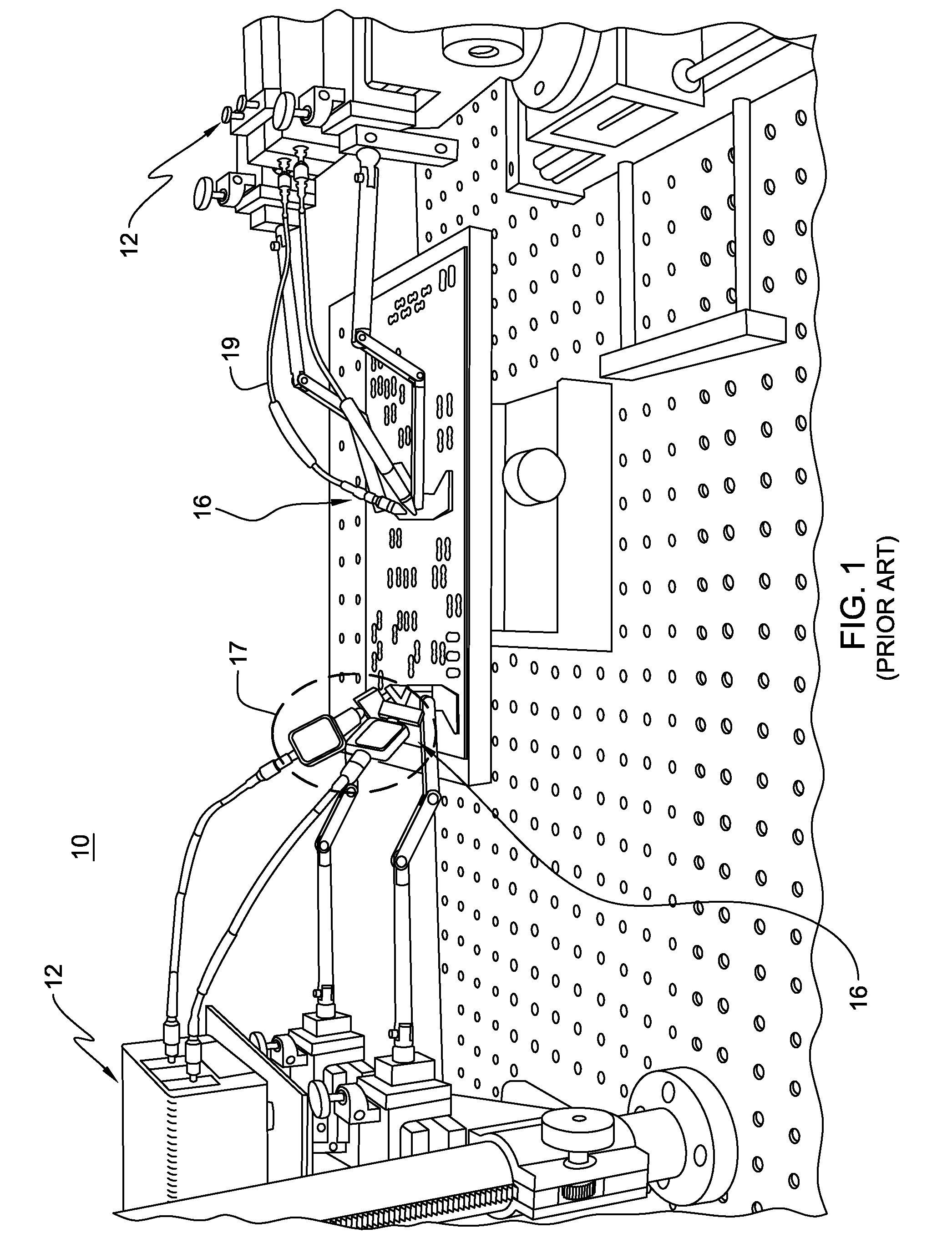
There currently exists limited techniques for providing time and frequency domain measurements from which transmission line models and material parameters for characterizing high frequency performance of printed-circuit board (PCB) conductor structures (i.e., transmission lines) may be extracted.
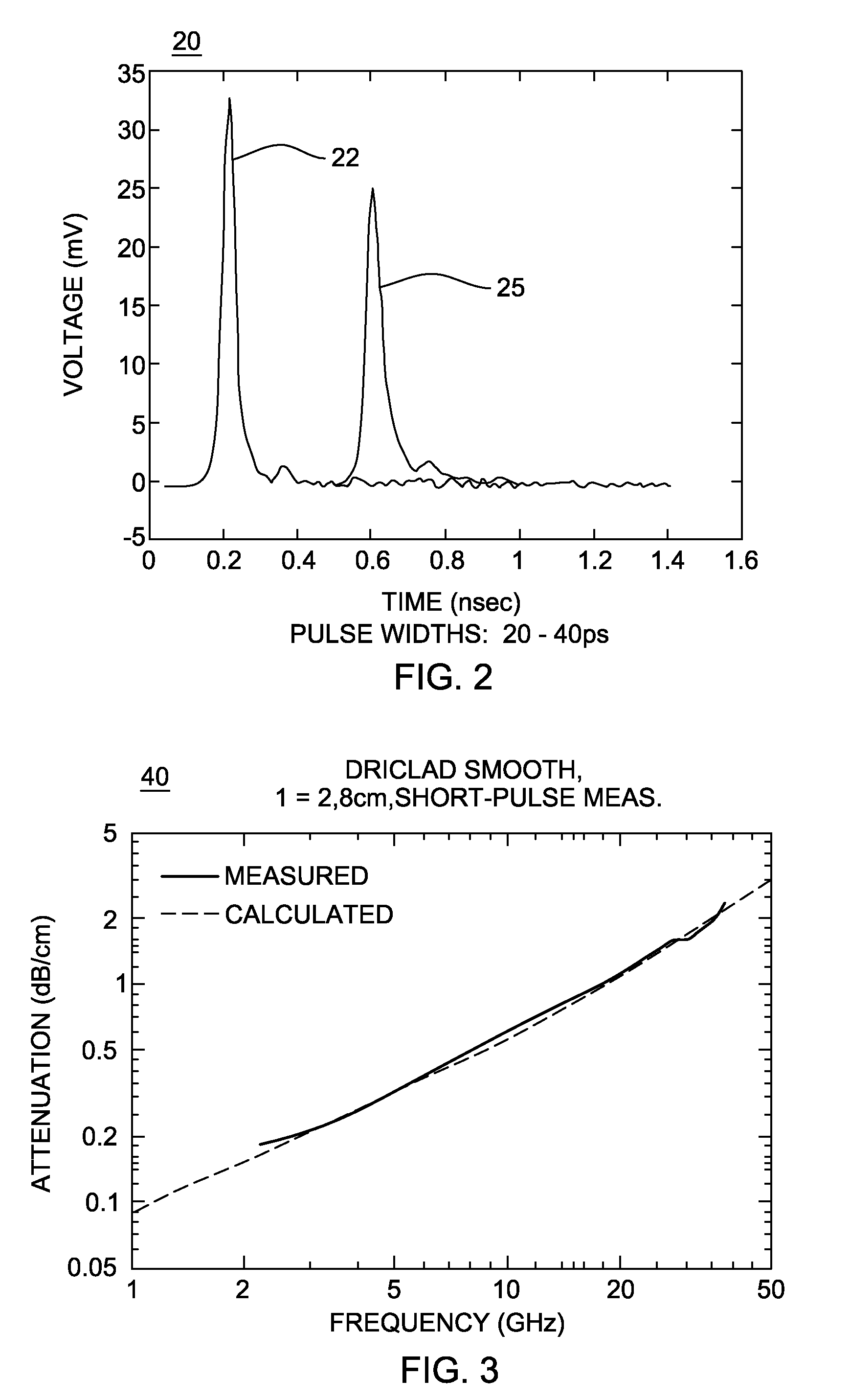
It is the case that typical VNA based measurements can generally obtain attenuation and phase, especially for high frequency range, but Zo(f) cannot be extracted due to the large discontinuities found in realistic multi-layer printed-circuit-boards, PCBs.
Non-causal models can cause inaccurate signal integrity and timing prediction and simulator convergence problem.
Further, lead-free compatibility imposes manufacturing constraints that impact electrical characteristics.
Moreover, simple TDR production-level Zo process monitors need to be improved because such techniques overpredict Zo due to losses on the board wiring.
Overprediction of Zo affects board design, cost, wireability, and system power.

Method used


Image

  • System and method implementing short-pulse propagation technique on production-level boards with incremental accuracy and productivity levels
  • System and method implementing short-pulse propagation technique on production-level boards with incremental accuracy and productivity levels
  • System and method implementing short-pulse propagation technique on production-level boards with incremental accuracy and productivity levels

Examples


Embodiment Construction

[0069]A preferred embodiment of the invention consisting of a description of the method employed and the necessary apparatus will now be described.

[0070]In one embodiment, a system and methodology of incorporating advanced measurement techniques for extracting electrical characteristics of interconnects on multi-layer production level printed circuit boards is provided. Bringing such test capability into the production environment is unique to this methodology.

[0071]FIG. 8 depicts a top view of a portion of a large production level PCB board 99. In an example embodiment, the PCB board in FIG. 8 is a large functional board, e.g., about ⅕ to ¼ inches thick and about 20 in. by 14 in. in area, for example, and may comprise a blend of glass fiber weave and epoxy-resin (e.g., bismaleimide triazine (BT)) as a substrate for use in printed circuit board wiring. According to the invention, the production board 99 is manufactured to include a test coupon 100 of small footprint including two or...


PUM


Abstract

A system and method for performing a test for characterizing high frequency operation of PCB boards. More particularly, a system and methodology is provided to implement a time-domain short pulse propagation (SPP) technique on the production line, on large, multi-layer, product-level PCB boards, for large volume testing, by people who are not familiar with advanced, delicate, measurement techniques, who need robust test facilities, and cannot afford the time or expense of other lab-type approaches.

Description

BACKGROUND OF THE INVENTION[0001]1. Field of the Invention[0002]The present invention relates generally to systems and techniques for modeling and characterizing printed-circuit board wiring, and particularly, to an improved system and method for generating more accurate transmission line models and characterizations for predicting performance of circuits and circuit structures as printed-circuit board transmission data-rates increase.[0003]2. Description of the Prior Art[0004]There currently exists limited techniques for providing time and frequency domain measurements from which transmission line models and material parameters for characterizing high frequency performance of printed-circuit board (PCB) conductor structures (i.e., transmission lines) may be extracted.[0005]One particular technique, known in the art as short-pulse-propagation, SPP, is a time-domain technique that may be employed to model and characterize performance of circuits and circuit structures. As described i...

Claims


Application Information

Patent Timeline
Patent Type & Authority Applications(United States)
IPC IPC(8): G01R31/02
CPCG01R31/2822G01R31/2818
Inventor DEUTSCH, ALINAKATOPIS, GEORGE A.KOPCSAY, GERARD V.KRABBENHOFT, ROGER S.SUROVIC, CHRISTOPHER W.
Owner GLOBALFOUNDRIES INC
Learn More