
Television frame and mounting system

a technology for television frames and mounting systems, which is applied in the direction of television systems, machine supports, other domestic objects, etc., can solve the problems of high price and specific flat panel display sizes of frames, and achieve the effect of preventing outward movement of flat panel televisions

Inactive Publication Date: 2010-11-04
NGUYEN DAI BAO NGOC
View PDF10 Cites 31 Cited by
  • Summary
  • Abstract
  • Description
  • Claims
  • Application Information

AI Technical Summary

Benefits of technology

"The present invention is a flat panel television-mounting device that allows for easy viewing of television screens of various sizes. The device includes a picture-type frame with a notched back and a glass pane that is supported by the frame. The glass pane has a removable central portion that creates a border around the removed central portion for exposure to the television screen. The device also includes indicia on the linen that outlines the various television screen sizes, making it easy to cut the liner. Additionally, the invention includes an attachment for securing the picture-type frame to a flat pane television and a scaffold for supporting the flat panel television to a wall. The invention allows for the television to appear as a painting or a work of art."

Problems solved by technology

Despite the relatively small thickness of these panels, compared to cathode ray tubes, they often distract from the décor of a room in which they are hung.
Heretofore, frames have been designed for a specific flat panel display size and as such are quite expensive.

Method used


Image

  • Television frame and mounting system
  • Television frame and mounting system
  • Television frame and mounting system

Examples


Embodiment Construction

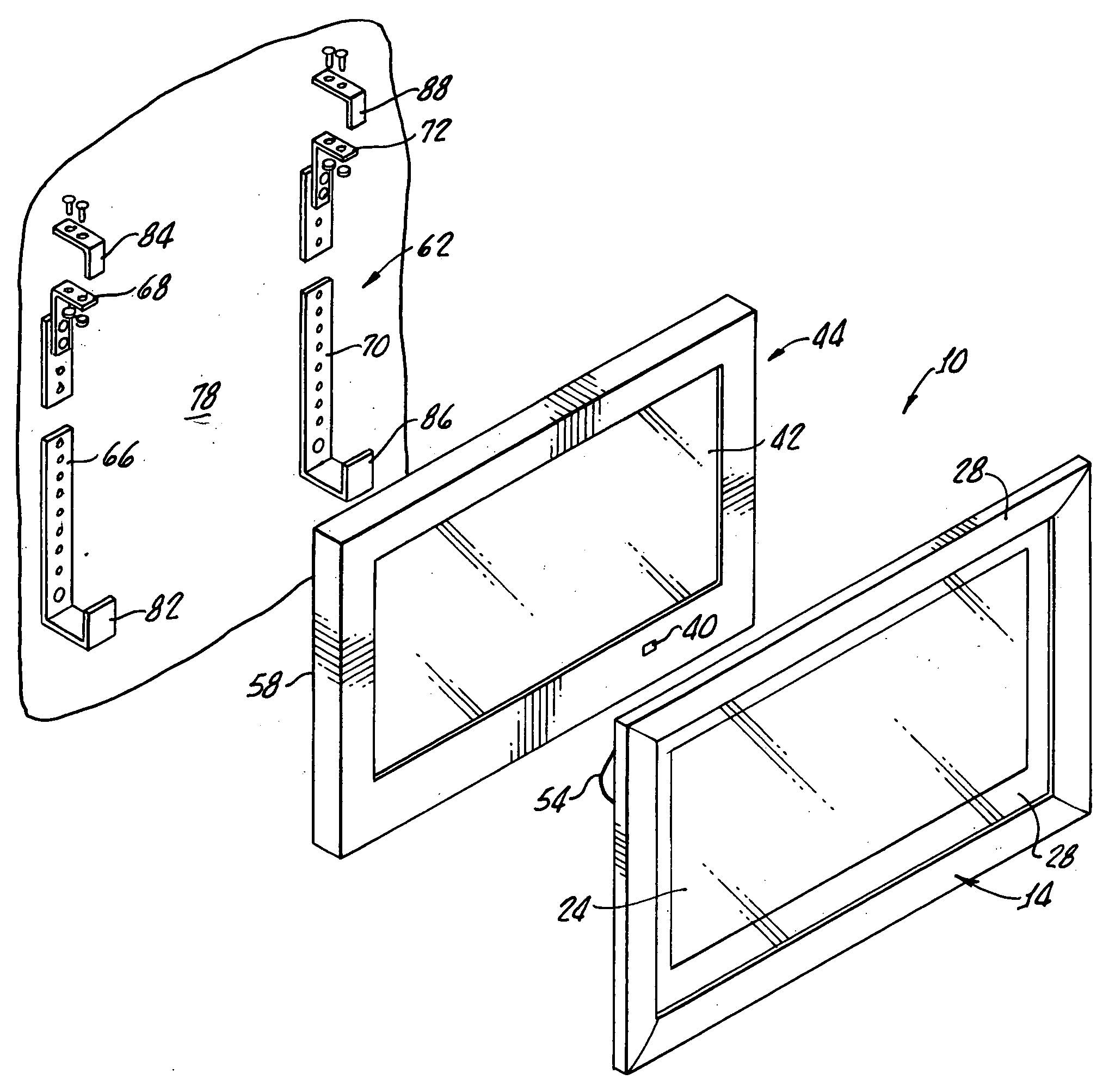
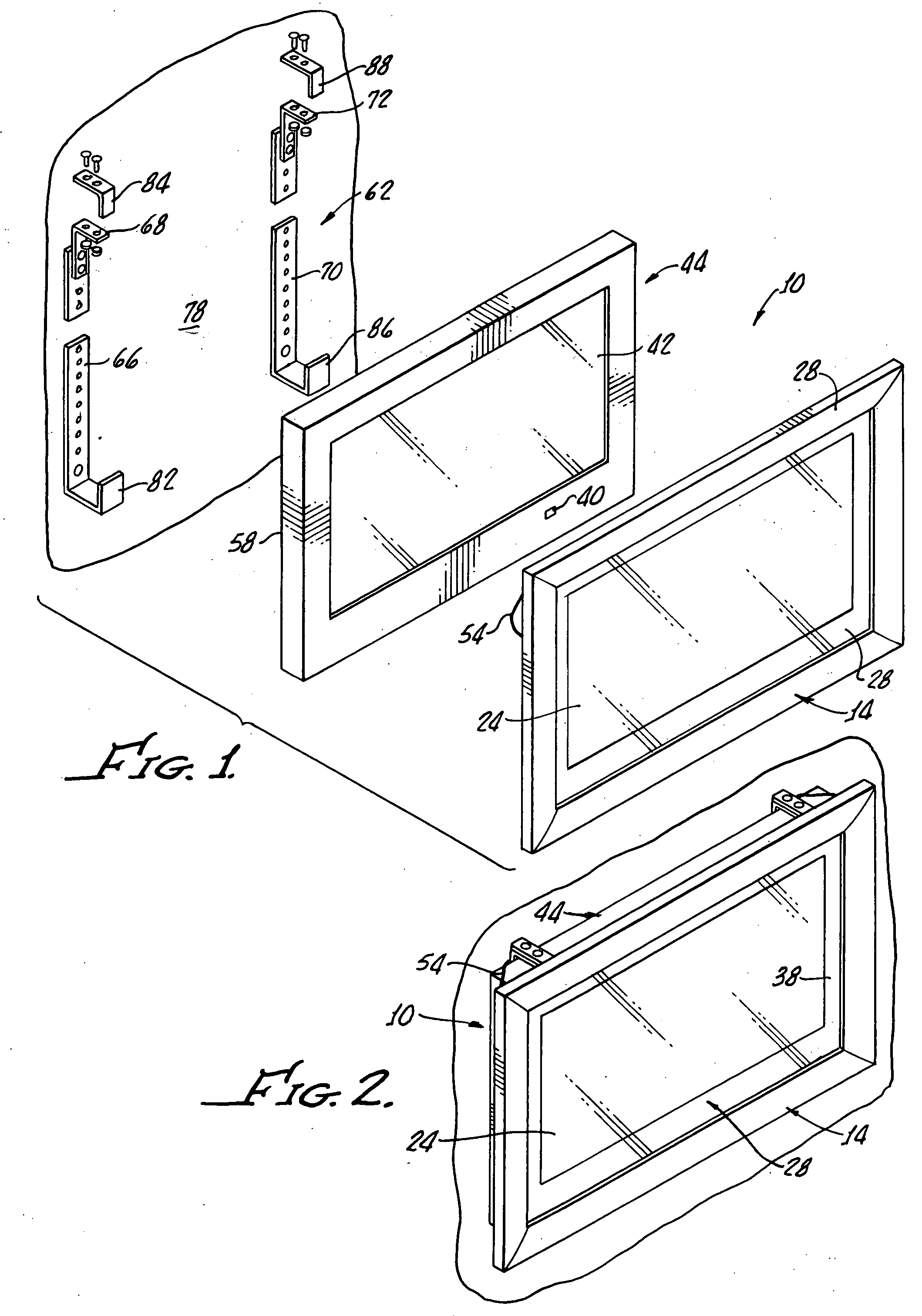
[0021]With reference to FIGS. 1-3, there is shown a flat panel, television mounting device 10, which generally includes a picture-type frame 14 having a notch 18 (FIG. 3) in a back 20 of the frame 14 for receiving a glass pane 24.

[0022]As best shown in FIGS. 4 and 5, a linen 28 is adhered to one side 32 of the glass pane 24 with a central portion 34 of the linen 28 removable from the glass pane 24 leaving a matte-like border 38 for exposing a screen 42 of a flat screen TV 44.

[0023]The linen 28 is removably adhered to the one side 32 of the glass pane 24 and indicia, such as broken lines 48, 50 provide cutting guides 48, 50 for various television screen sizes, the linen being shown cut along the line 48 to expose the central portion 34.

[0024]The linen, being transparent to infrared eliminates the need and expensive costs of remote relay systems necessary with conventional television frames. Thus, the linen 28 by way of the remaining border 38 enables passage of an infrared signal to ...


PUM


Abstract

A flat panel television mounting device includes a picture-type frame having a notch back surrounding an open central area along with a glass pane sized for reception by the notch back and supported by the frame. A linen is provided and adhered to one side of the glass pane with a central portion of the linen removable from the glass pane leaving a border around the removed central portion for exposing a television screen when the glass pane is disposed thereagainst.

Description

[0001]The present invention generally relates to cover frame assemblies for mounting onto a flat panel display such as a high-definition television set. More particularly, the present invention provides for a frame suitable for use with various size flat panel televisions.[0002]Flat panel displays such as plasma and LCD panels have become increasingly common and will gradually replace virtually all cathode ray tube televisions and displays.[0003]Flat panel televisions and displays are frequently hung on a wall in a manner resembling paintings and various mounting frames have been devised for attaching such flat panel displays to a wall.[0004]Despite the relatively small thickness of these panels, compared to cathode ray tubes, they often distract from the décor of a room in which they are hung.[0005]Heretofore, frames have been designed for a specific flat panel display size and as such are quite expensive.[0006]There is a needed a flat panel television frame or mounting device that...

Claims


Application Information

Patent Timeline
Patent Type & Authority Applications(United States)
IPC IPC(8): A47G1/16A47F7/00F16M13/02A47G1/06
CPCH04N5/655H04N5/65
Inventor NGUYEN, DAI BAO NGOC
Owner NGUYEN DAI BAO NGOC
Learn More