
Supply-Regulated Phase-Locked Loop (PLL) and Method of Using

a phase-locked loop and supply-regulated technology, applied in the field of phase-locked loops, can solve the problems of increasing the difficulty of designing plls with desirable characteristics, reducing the performance of plls, and increasing phase noise or timing jitter, so as to maintain the stability of pll operation

Inactive Publication Date: 2010-10-28
QUALCOMM INC
View PDF10 Cites 42 Cited by
  • Summary
  • Abstract
  • Description
  • Claims
  • Application Information

AI Technical Summary

Benefits of technology

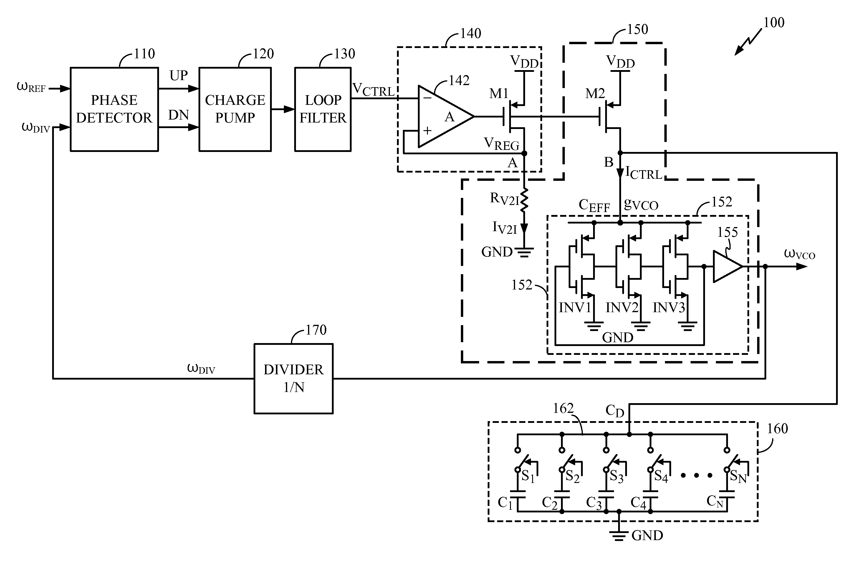
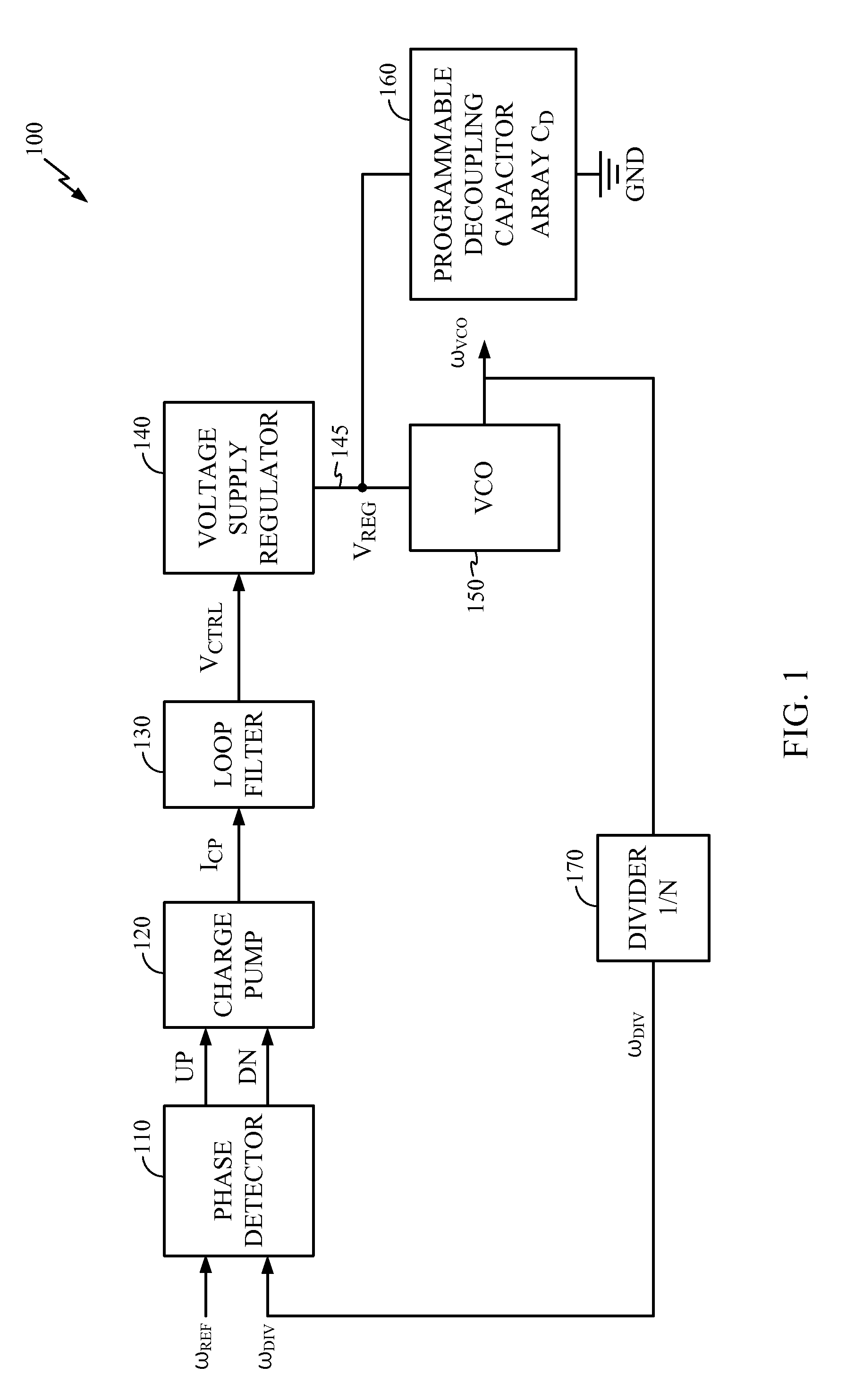
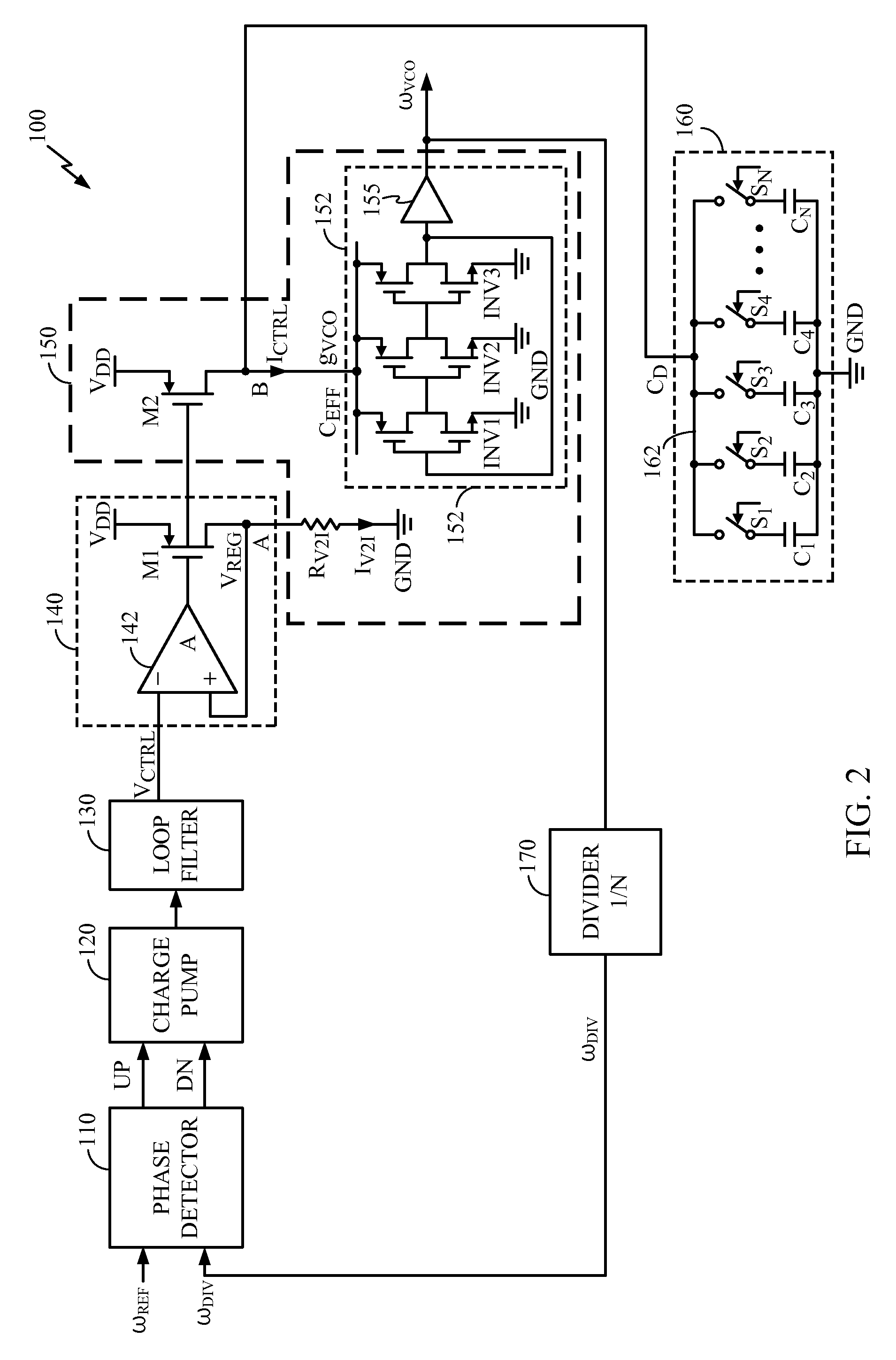
[0008]These and other problems are generally solved or circumvented, and technical advantages are generally achieved, by preferred embodiments of the present invention which provide a supply-regulated PLL. The PLL comprises a supply-regulating loop, a voltage-controlled oscillator (VCO), and a programmable decoupling capacitor array for the VCO. The capacitance of the VCO decoupling capacitor array is adjustable to be equal to N time CUNIT, where N is the current value of a multiplication factor of a divide-by-N circuit and CUNIT is a unit capacitance characterized for a processing technology chosen for fabricating the decoupling capacitor array. When the PLL switches from one frequency band to another, a higher-order pole introduced by the VCO decoupling capacitor tracks the PLL reference frequency, thus maintaining the PLL operational stability across a wide range of reference frequencies. Also, the ratio of higher-order pole frequency to the PLL reference frequency is determined solely by a ratio of capacitances which is generally immune to PVT variations in modern process technologies. As a result, the operational stability of the supply-regulated PLL is now less sensitive to PVT variations and the PLL can be used with a wider range of reference frequencies.

Problems solved by technology

While CMOS manufacturing technologies continue scaling down into the deep-submicron and nanometer range, design of PLLs with desirable characteristics is becoming increasingly difficult.
One of the many challenges comes from increased sensitivity to on-chip power supply noise due to the reduced supply-to-threshold voltage ratios, which degrades PLL performance, by causing increased phase noise or timing jitter.
More specifically, a voltage controlled oscillator (VCO) or a current controlled oscillator (CCO) used in a PLL is particularly sensitive to noise on its power supply.
This and other existing supply-regulated PLL structures, however, exhibit a number of apparent problems.
This may lead to increased power consumption in the PLL.
Second, the use of the VCO decoupling capacitor introduces a higher-order pole which makes compensating the PLL loop difficult.

Method used


Image

  • Supply-Regulated Phase-Locked Loop (PLL) and Method of Using
  • Supply-Regulated Phase-Locked Loop (PLL) and Method of Using
  • Supply-Regulated Phase-Locked Loop (PLL) and Method of Using

Examples


Embodiment Construction

[0020]The making and using of the presently preferred embodiments are discussed in detail below. It should be appreciated, however, that the present invention provides many applicable inventive concepts that can be embodied in a wide variety of specific contexts. The specific embodiments discussed are merely illustrative of specific ways to make and use the invention, and do not limit the scope of the invention.

[0021]The present invention will be described with respect to preferred embodiments in a specific context, namely supply-regulated PLLs with a PVT and multiplication factor independent higher order pole that tracks the PLL reference frequency, therefore providing an improved overall PLL operational stability, among other advantageous features. These advantageous features may be particularly desirable in a PLL used as a general purpose clock multiplier, for example. Embodiments of the present invention may be applied to PLLs used in applications where improved operational stab...


PUM


Abstract

A supply-regulated Phase-locked loop (PLL) is provided. The PLL comprises a supply-regulating loop, a voltage-controlled oscillator (VCO), and a programmable decoupling capacitor array for the VCO. The capacitance of the VCO decoupling capacitor array is adjustable to be equal to N times CUNIT, where N is the current value of a multiplication factor of a divide-by-N circuit and CUNIT is a unit capacitance characterized for a processing technology chosen for fabricating the decoupling capacitor array. When the PLL switches from one frequency band to another, a higher-order pole introduced by the VCO decoupling capacitor tracks the PLL reference frequency, thus improving the PLL operational stability.

Description

TECHNICAL FIELD[0001]The present invention relates generally to phase-locked loops, and more particularly to a supply-regulated PLL and method of using.BACKGROUND[0002]A phase-locked loop (PLL) is an electronic system that locks in phase and frequency of an output signal to the phase and frequency of an input signal. A PLL is widely used in applications in communication systems and devices, such as FM demodulators, stereo demodulators, tone detectors, frequency synthesizers, etc. A PLL is also commonly employed in digital applications that require a high-frequency periodic signal to synchronize the events between high-performance digital circuits, such as microprocessors, digital signal processors, network processors, synchronous systems, and the like. A PLL is particularly desirable to be integrated with semiconductor integrated circuits (IC) for the various application fields, and implemented by advanced Very-Large-Scale-Integrated-Circuit (VLSI) manufacturing technologies, such a...

Claims


Application Information

Patent Timeline
Patent Type & Authority Applications(United States)
IPC IPC(8): H03L7/00
CPCH03L7/22H03L7/099
Inventor RAGHUNATHAN, ASHWINPEDRALI-NOY, MARZIO
Owner QUALCOMM INC
Learn More