
Method for analyzing the structure of an electrically conductive object

a technology structures, applied in the field of methods for analyzing the structure of electrically conductive objects, can solve the problems of insufficient variation of individual electrical impedance properties to enable accurate analysis, and achieve the effect of better separating between different morphologies

Active Publication Date: 2010-10-21
WANG WEI
View PDF1 Cites 15 Cited by
  • Summary
  • Abstract
  • Description
  • Claims
  • Application Information

AI Technical Summary

Benefits of technology

[0006]It is therefore desirable to be able to bette...

Problems solved by technology

However, the amount of variation of the individual electrical impedance properties may be insufficient to enable accurate analysis.

Method used


Image

  • Method for analyzing the structure of an electrically conductive object
  • Method for analyzing the structure of an electrically conductive object
  • Method for analyzing the structure of an electrically conductive object

Examples


Embodiment Construction

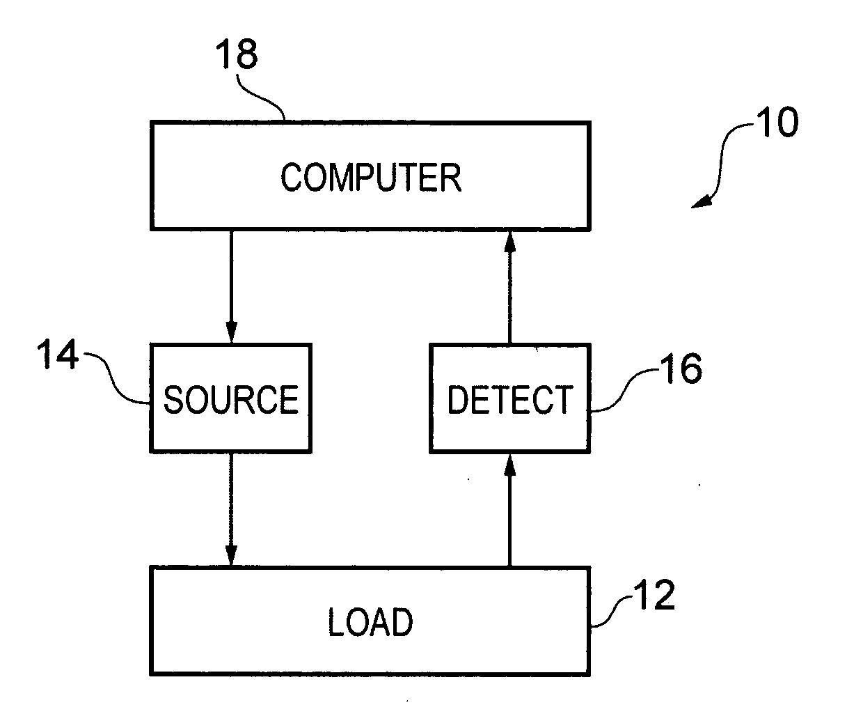
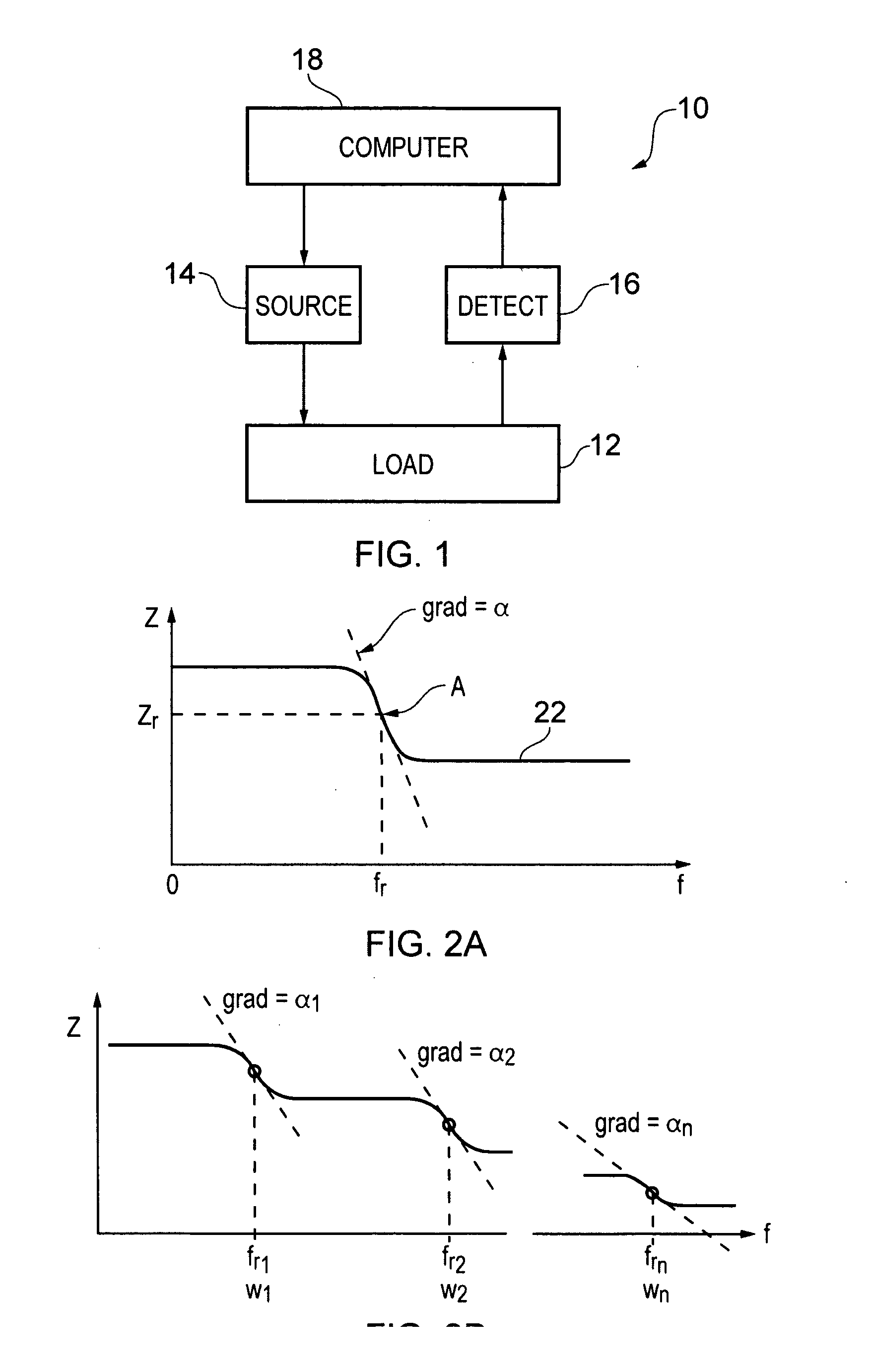
[0035]FIG. 1 illustrates diagrammatically electrical impedance measurement or electrical impedance tomography (EIT) apparatus 10 for measuring impedance data for a load 12. The load 12 comprises an electrically conductive object to which are attached a plurality of electrodes. The term ‘electrically conductive’ means that the object is capable of conducting an electric current but it does not necessarily need to conduct current very well. The apparatus 10 further comprises a signal source 14, a signal detector 16 and a computer 18. In one embodiment, the signal source provides, as an input signal, an electric current and the signal detector detects, as an output signal, voltage. In another embodiment, the signal source provides, as an input signal, a voltage and the signal detector detects, as an output signal, electric current.

[0036]The computer typically comprises at least a processor and a memory. The memory stores a computer program which when loaded into the processor controls ...


PUM


Abstract

A method for analyzing the structure of an electrically conductive object, the method comprising the steps of: (i) obtaining electrical impedance data for the object over a range of frequencies; (ii) analyzing the obtained electrical impedance data using a transfer function of an assumed electrical model to determine a plurality of electrical impedance properties for the object; (iii) constructively combining selected ones of the determined plurality of electrical impedance properties to provide at least one parametric impedance value for the object; and (iii) imaging one or more of the determined parametric impedance values.

Description

CROSS REFERENCE TO RELATED APPLICATIONS[0001]This application is the U.S. National Stage of International Application Number PCT / IB08 / 001,982 filed on Jun. 6, 2008 which was published in English on Dec. 11, 2008 under International Publication Number WO 2008 / 149125.FIELD OF THE INVENTION[0002]Embodiments of the present invention relate to a method for analyzing the structure of an electrically conductive object.BACKGROUND TO THE INVENTION[0003]Electrical impedance tomography (EIT) is a known imaging technique, particularly used in medical and other applications for the detection of underlying morphology. Typically, a plurality of electrodes is attached to an object to be imaged. Either input voltages are applied across a subset of ‘input’ electrodes and output electric currents are measured at ‘output’ electrodes, or input electric currents are applied between a subset of ‘input’ electrodes and output voltages are measured at ‘output’ electrodes or between pairs of output electrodes...

Claims


Application Information

Patent Timeline
IPC IPC(8): A61B5/053
CPCA61B5/0536
Inventor WANG, WEI
Owner WANG WEI
Learn More