Microscopy imaging phantoms

a technology of microscopy and imaging phantoms, applied in the field of imaging phantoms, can solve the problems of not providing the representation of complex biological structures desired in an imaging phantom, the standard is not suitable for representation, and the development of imaging standards is less well-developed. , to achieve the effect of reducing the quality of the resultant image, and limiting the full visualisation of the specimen

Inactive Publication Date: 2010-10-14
GE HEALTHCARE LTD
View PDF12 Cites 12 Cited by
  • Summary
  • Abstract
  • Description
  • Claims
  • Application Information

AI Technical Summary

Benefits of technology

[0041]Suitably, the imaging microscope parameter is selected to be a predetermined instrument setting, such as illumination intensity or filtration. Obtaining optimal resolution, sensitivity and image quality in any microscope is highly dependent on even illumination of the specimen. Any gradient in illumination intensity across the field of view has the potential to reduce the quality of the resultant image and limit the full visualisation of the specimen. Use of the imaging phantom to regularly check the illumination intensity and evenness at different times allows users of microscopes to maintain their equipment in an optimal configuration. Since the imaging phantom is stable and invariant, unlike a biological specimen which may be subject to damage of fading precluding reproducible imaging, images may recorded at different times and by use of appropriate image analysis software quantitatively compared to ensure that the microscope is performing within desired parameters. For example, an imaging phantom comprising a group or collection of detectable composite elements may be constructed to represent a population of cells dispersed over an imaging area. Imaging of the phantom is undertaken using a microscope set to provide optimal illumination, one or more images are captured digitally and processed using image analysis software to produce quantitative data, for example, the number of objects / image, the mean size of objects etc. Repeating the imaging process at a later time and generating the same data allows a quantitative comparison between the two data sets which allows the operator to determine whether the microscope is still operating optimally or whether some adjustment is required. For example, if the second data set shows that fewer objects were detected than in the first data set this may indicate that the microscope illumination has become sub-optimal reducing the sensitivity or resolution of the system.
[0042]Use of the same imaging phantoms for instrument calibration permits reliable luminescent measurement and enables more than one instrument to be set to the same calibration standard. It is therefore to be preferred that the visualisation agents employed in imaging phantoms as described herein are stable and not subject to physical or chemical degradation or photobleaching.
[0043]In a fifth aspect, the invention provides a method for calibration and / or validation and / or optimisation of image analysis software. The method comprises: providing an imaging microscope; providing suitable image analysis software for quantitative analysis of images produced by said microscope; providing one or more imaging phantoms as described herein; acquiring one or more images of the or each imaging phantom; using the analysis software to produce quantitative data from at least one of said images; and using the data to quantitatively determine the performance of said software for image analysis with reference to known characteristics of the said imaging phantoms. For example an imaging phantom may be prepared with a pre-determined density of detectable internal elements which have a fixed or variant spacing within a known range determined by the method of construction (e.g. the size of spacer elements between the detectable elements). Such a phantom may be representative of cultured cells growing on a planar surface. To optimise or validate image analysis software, the phantom is imaged and the resulting images analysed using the software under test to determine whether the quantitative data produced by the software correlates with the known parameters of the phantom. For example, imaging of a fluorescent phantom comprising a population of dispersed detectable elements of known area at known frequency / unit area, segmentation of the image by thresholding intensity values within the image to delineate objects and calculation of object area and frequency / area and comparison of data with the known values provides quantitative means for validating the performance of image analysis software to analyse a particular biological specimen represented by the phantom. Furthermore the same procedure may be used to optimise settings, e.g. threshold settings used for image segmentation, within the image analysis software to produce optimal results, i.e. as close as possible to the known values. In this aspect, the phantom has the advantage over a biological specimen in having known values for size, density of objects etc. since the phantom is constructed to pre-determined specifications.

Problems solved by technology

In the field of microscopy, calibration and imaging standards are less well developed.
However, in flow cytometry the instrumentation measures only intensity information and consequently while beads developed for calibration of flow cytometry instruments may be used for intensity and alignment calibration in fluorescence microscopes, they do not provide a representation of complex biological structures desired in an imaging phantom.
While such a device is suitable for determining the optical resolution of a microscope or other imager for resolving structures disposed in regular patterns, e.g. a nucleic acid microarray, the standard is not suitable for representing the natural variation inherent in a biological sample and the method of construction precludes use of multiple fluors or other imaging agents within a single device.
Consequently the device of US 2007 / 0190566 has significant limitations as a biologically representative imaging phantom suitable for cellular and tissue imaging applications.
These devices are suitable as resolution standards but have considerable limitations as true biological imaging phantoms.
This device has the benefit of stable fluorescence provided by the inorganic phosphors, but suffers from the same limitations as a biologically representative phantom as described above for devices and methods.
This method produces a stable specimen which may be used to test sensitivity and image alignment in fluorescent microscopy, however the discrete nature of the fluorescent sources used and their uncontrolled distribution renders this method unsuitable for producing microscopy imaging phantoms which represent biological structures with defined separation and inclusion of structures within other structures.

Method used


Image

  • Microscopy imaging phantoms
  • Microscopy imaging phantoms
  • Microscopy imaging phantoms

Examples


Embodiment Construction

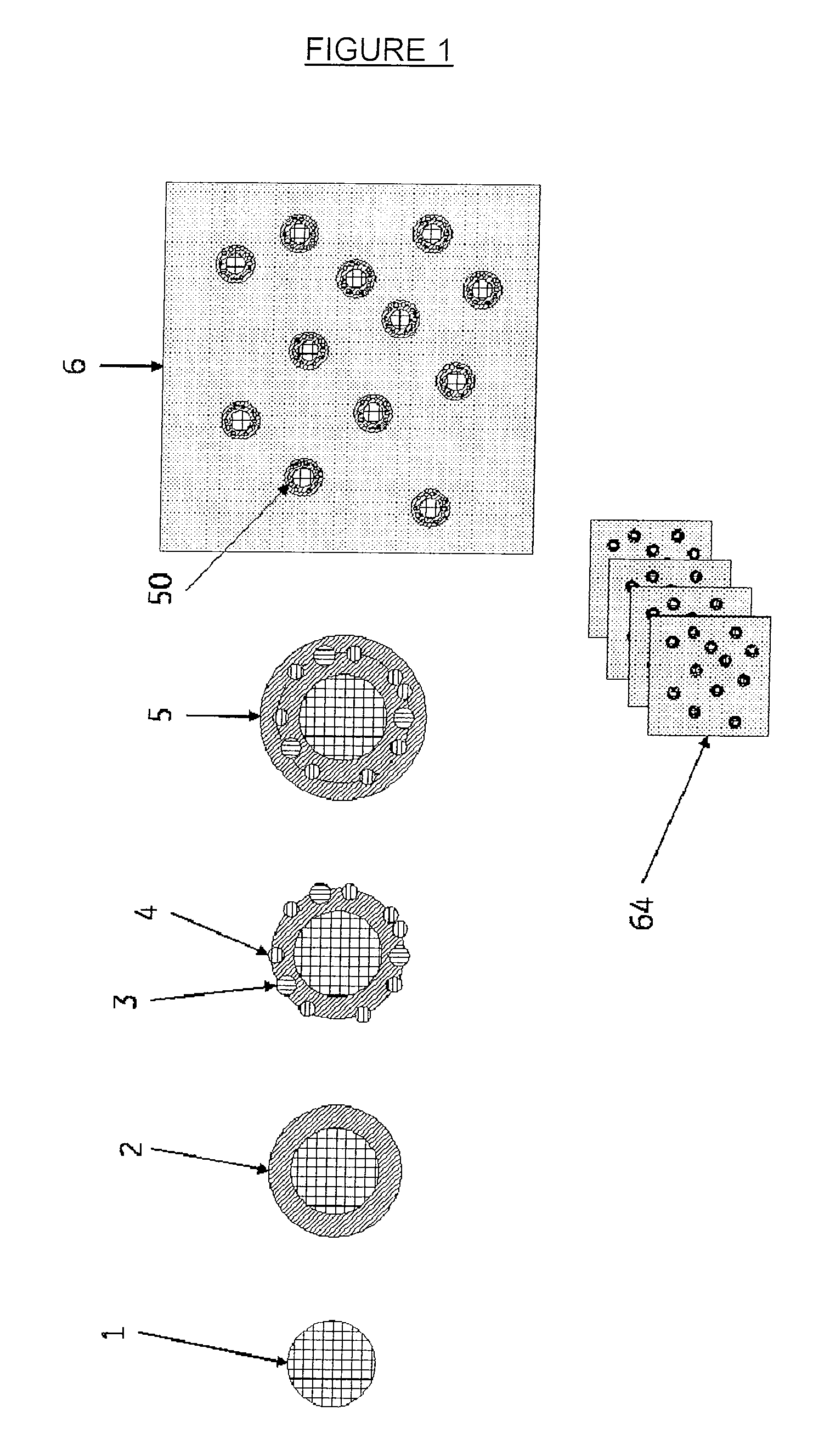
[0050]A polymeric matrix material in the form of an elongated solid structure (or block) may be produced by means of a number of alternative techniques depending on whether a regular (ordered) array of internal elements are desired or whether the internal elements are disposed in the matrix in a random or irregular manner. For example, in one procedure, imaging blocks may be produced by a sequential dipping and rolling process as shown in FIG. 1. A polymer rod [1] is used as the core of the phantoms to represent a cell nucleus. The rod may comprise a plastic or other polymer containing a coloured dye, a fluorescent dye, a refractive index modifier or any other agent suitable for visualisation by the microscopy technique to be employed in imaging the phantom. For example, for a cell phantom to be used for fluorescent microscopy the rod may comprise a polymer containing CY™5 (GE Healthcare).

[0051]The core rod is dipped one or more times into a melt or viscous solution of a second poly...


PUM

PropertyMeasurementUnit
wavelengthsaaaaaaaaaa
diameteraaaaaaaaaa

Abstract

The invention relates to imaging phantoms for validation, optimisation and calibration of microscopy instrumentation and software used for analysis of microscope images. The materials and methods of the invention find particular use in high content screening and high content analysis.

Description

CROSS-REFERENCE TO RELATED APPLICATIONS[0001]This application is a filing under 35 U.S.C. §371 and claims priority to international patent application number PCT / EP2008 / 064656 filed Oct. 29, 2008, published on May 7, 2009, as WO 2009 / 056560, which claims priority to application number 0721564.3 filed in Great Britain on Nov. 2, 2007.FIELD OF THE INVENTION[0002]The present invention relates to imaging phantoms for validation, optimisation and calibration of microscopy instrumentation and software used for analysis of microscope images.BACKGROUND OF THE INVENTION[0003]The use of imaging phantoms (synthetic models of biological specimens) is common in 3D imaging at a macro scale with X-ray, CT, PET, ultrasound and MRI instruments intended for imaging of animals and humans (Pogue, B. W. and Patterson, M. S., J. Biomed. Opt., (2006), 11(4), 041102; J. Neurosurg., (2004), 101(2), 314-22.). Phantoms allow development and validation of new imaging applications as well as providing an invari...

Claims


Application Information

Patent Timeline
Patent Type & Authority Applications(United States)
IPC IPC(8): C08L101/00G06F15/00G06F9/44
CPCG01N21/6458G01N21/278
Inventor THOMAS, NICHOLAS
Owner GE HEALTHCARE LTD
Why Eureka
Try Eureka