Exhaust emission control device

a technology of exhaust emission control and control device, which is applied in the direction of machines/engines, mechanical equipment, transportation and packaging, etc., can solve problems such as the inability to mount on a vehicl

Active Publication Date: 2010-10-14
HINO MOTORS LTD
View PDF6 Cites 21 Cited by
  • Summary
  • Abstract
  • Description
  • Claims
  • Application Information

AI Technical Summary

Benefits of technology

[0022]According to the above-mentioned exhaust emission control device of the invention, various effects and advantages may be obtained as follows.(I) A swirling flow is effectively formed in the entry end of the mixing pipe and the urea water is added to the swirling flow formed, which facilitates dispersion of the urea water and facilitates collision of the urea water against the inner periphery of the mixing pipe; as a result, mist particles of the urea water can be effectively miniaturized and early decomposed into ammonia and carbon dioxide gas. Moreover, without the outer periphery of the discharge end of the gas gathering chamber being covered with heat-insulating material such as glass wool, only by ensuring the extra space isolated from the gas guide passages in the gas gathering chamber as the heat-retention chamber surrounding the entry end of the mixing pipe, the inner periphery of the entry end of the mixing pipe can be kept high-temperatured and the colliding urea water can be favorably decomposed into ammonia without deposition as solid urea; as a result, the use of a costly heat-retention structure using heat-insulating material such as glass wool can be eliminated to attain substantial lessening in production cost.(II) By circumferentially cutting in the entry end of the mixing pipe to provide the U-shaped notch line, by bending the rectangular portion defined by the notch line radially outward to provide the opening, and by employing the bent rectangular portion as the mostdownstream guide fin for tangential introduction of the exhaust gas from the discharge side of the particulate filter to the opening, any step formed by attachment of a mostdownstream guide fin as separate part to the edge of the opening can be eliminated and the guide surface of the guide fin can be made contiguous with the inner periphery of the mixing pipe. As a result, deviations on performance such as swirling flow strength and / or exhaust resistance associated with deviation in assembling accuracy can be lessened. Furthermore, assembling efficiency can be also enhanced in comparison with a case where the mostdownstream guide fin is attached as separate part to the edge of the opening.

Problems solved by technology

However, such arrangement of the particulate filter and the selective reduction catalyst substantially spaced apart from each other will extremely impair the mountability on a vehicle.

Method used


Image

  • Exhaust emission control device
  • Exhaust emission control device
  • Exhaust emission control device

Examples


Embodiment Construction

[0047]Embodiments of the invention will be described in conjunction with the drawings.

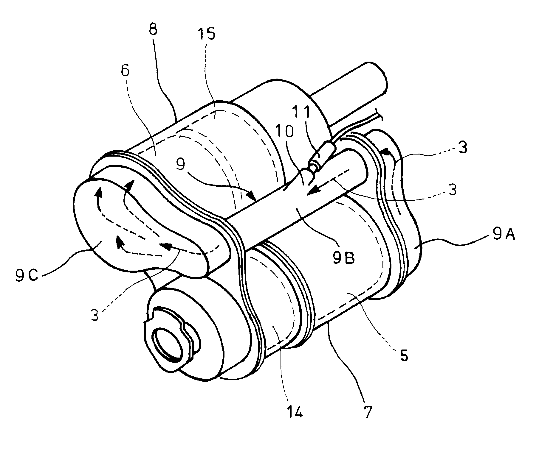
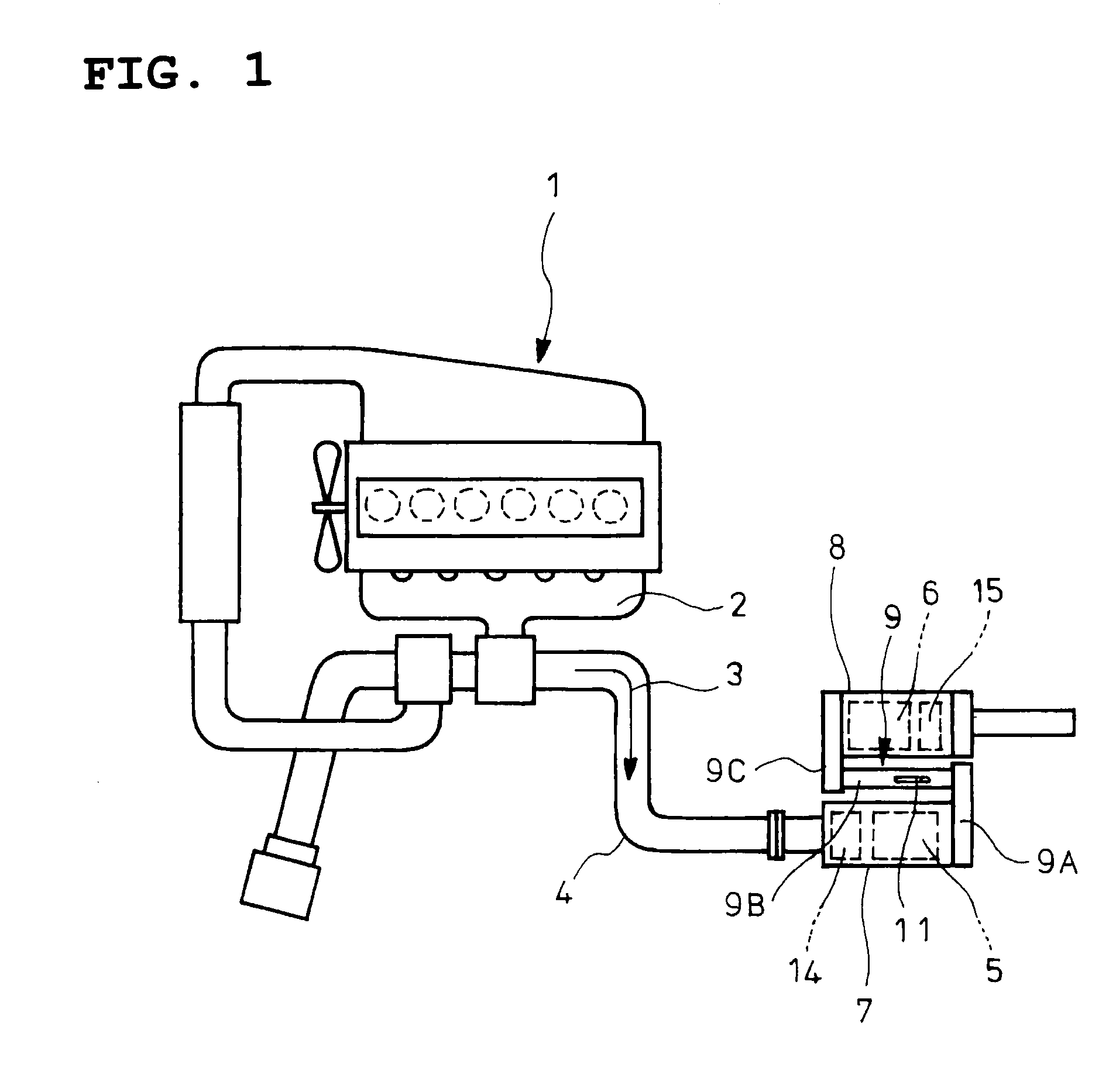
[0048]FIGS. 6 and 7 show an embodiment of the invention directed to an exhaust emission control device which has a basic structure substantially similar to that of the above-mentioned exhaust emission control device shown in FIGS. 1 and 2 and which has changes as mentioned in the below as to an upstream portion of a communication passage 9 constituted by a gas gathering chamber 9A and a mixing pipe 9B.

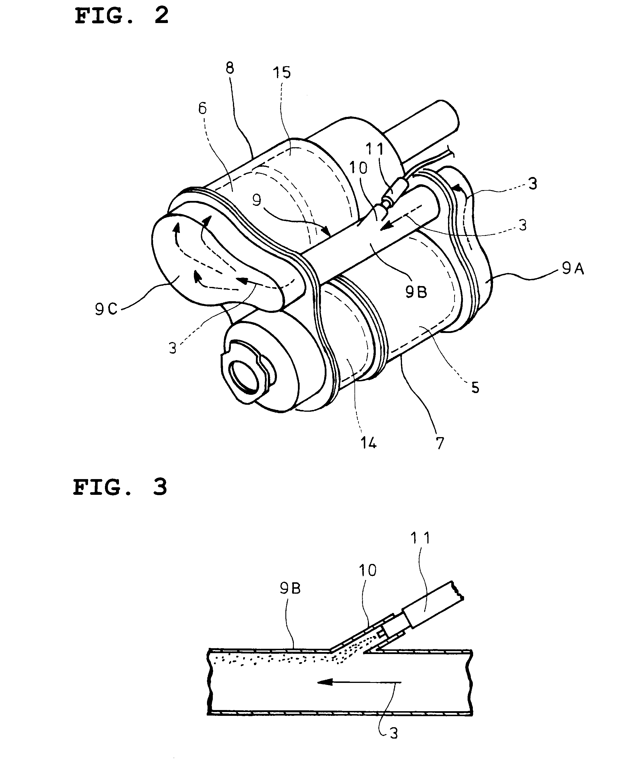
[0049]Specifically, in the embodiment illustrated, a discharge end of the gas gathering chamber 9A is connected to an entry end of the mixing pipe 9B so as to encase the entry end of the mixing pipe 9B and close an opened end face of the entry end in a required spaced-apart relationship. A side surface of the entry end of the mixing pipe 9B adjacent to the discharge side of the particulate filter 5 is formed with an opening 12. Gas guide passages 13 are formed in the gas gathering chamber 9A by guide ...


PUM

PropertyMeasurementUnit
sizeaaaaaaaaaa
flow rateaaaaaaaaaa
heat retentionaaaaaaaaaa

Abstract

An object of the invention is to provide an exhaust emission control device which eliminates the use of a heat-retention structure using heat-insulating material such as glass wool so as to attain substantial lessening in production cost. A discharge end of a gas gathering chamber is connected to an entry end of a mixing pipe so as to encase the entry end of the mixing pipe and close an opened end face in a required spaced-apart relationship. Moreover, a side surface of the entry end of the mixing pipe adjacent to the discharge side of the particulate filter is formed with an opening; and gas guide passages are formed in the gas gathering chamber by guide fins for tangential introduction of all of the exhaust gas from the discharge side of the particulate filter to the opening. An extra space isolated from the gas guide passages is ensured in the gas gathering chamber as a heat-retention chamber surrounding the entry end of the mixing pipe.

Description

TECHNICAL FIELD[0001]The present invention relates to an exhaust emission control device.BACKGROUND ART[0002]It has been recently proposed that a particulate filter for capturing particulates in exhaust gas is incorporated in an exhaust pipe and a selective reduction catalyst capable of selectively reacting NOx with ammonia even in the presence of oxygen is arranged downstream of the particulate filter, urea water as reducing agent being added between the selective reduction catalyst and the particulate filter, thereby attaining lessening of both the particulates and NOx.[0003]Such addition of the urea water to the selective reduction catalyst is conducted between the particulate filter and the selective reduction catalyst. Thus, in order to ensure sufficient reaction time for pyrolysis of the urea water added to the exhaust gas into ammonia and carbon dioxide gas, it is necessary to prolong a distance between a urea water added position and the selective reduction catalyst. However...

Claims


Application Information

Patent Timeline
Patent Type & Authority Applications(United States)
IPC IPC(8): F01N3/035
CPCF01N3/035F01N3/106F01N3/108F01N3/2066F01N3/2892F01N13/0097F01N2240/20F01N2470/18F01N2470/22F01N2610/02Y02T10/24F01N13/08Y02T10/12B01F23/2132B01F2025/931B01F25/10B01F25/3141
Inventor KOWADA, MINORU
Owner HINO MOTORS LTD
Why Eureka
Try Eureka