
Sensor system

Active Publication Date: 2010-10-07
SONOMEDICAL
View PDF9 Cites 34 Cited by
  • Summary
  • Abstract
  • Description
  • Claims
  • Application Information

AI Technical Summary

Benefits of technology

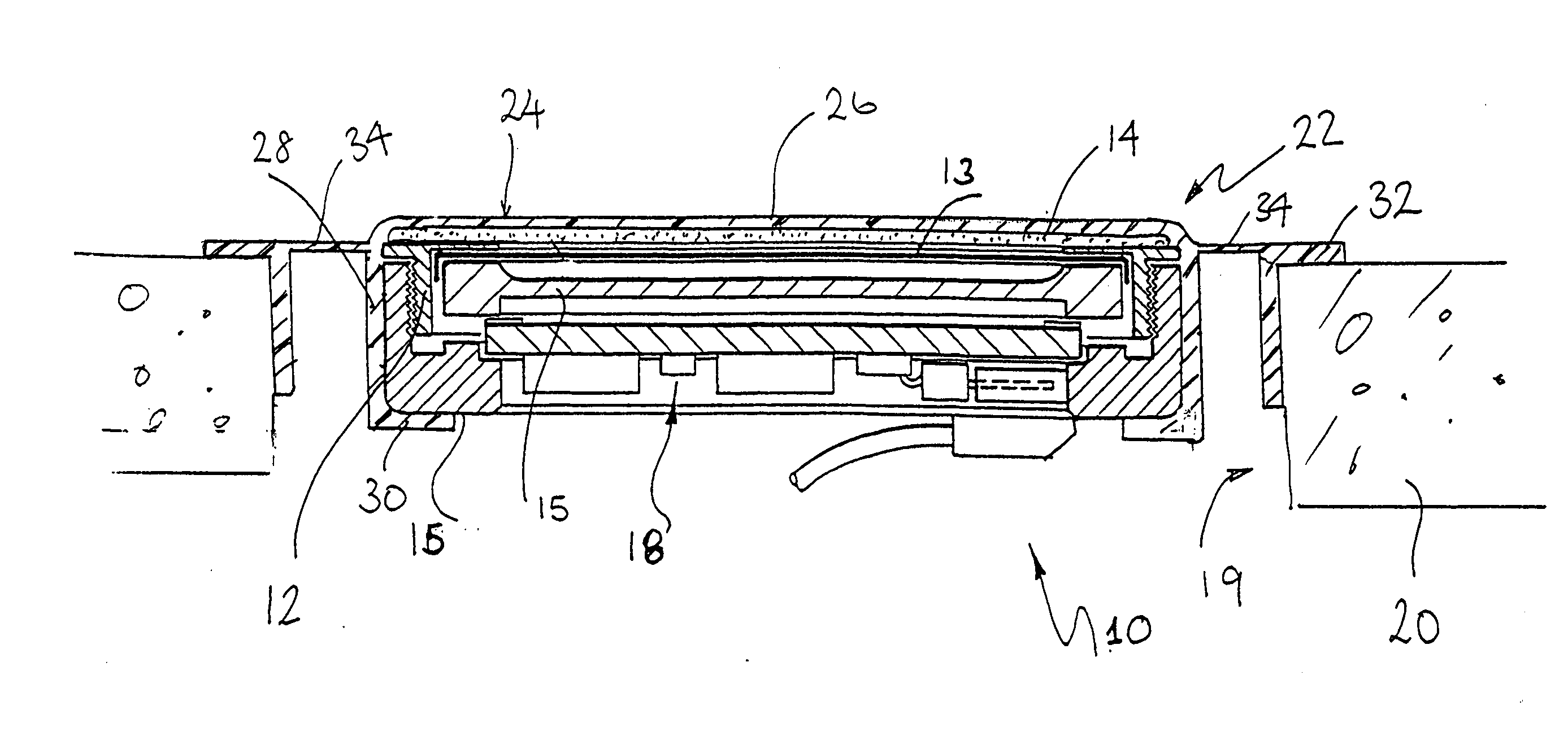
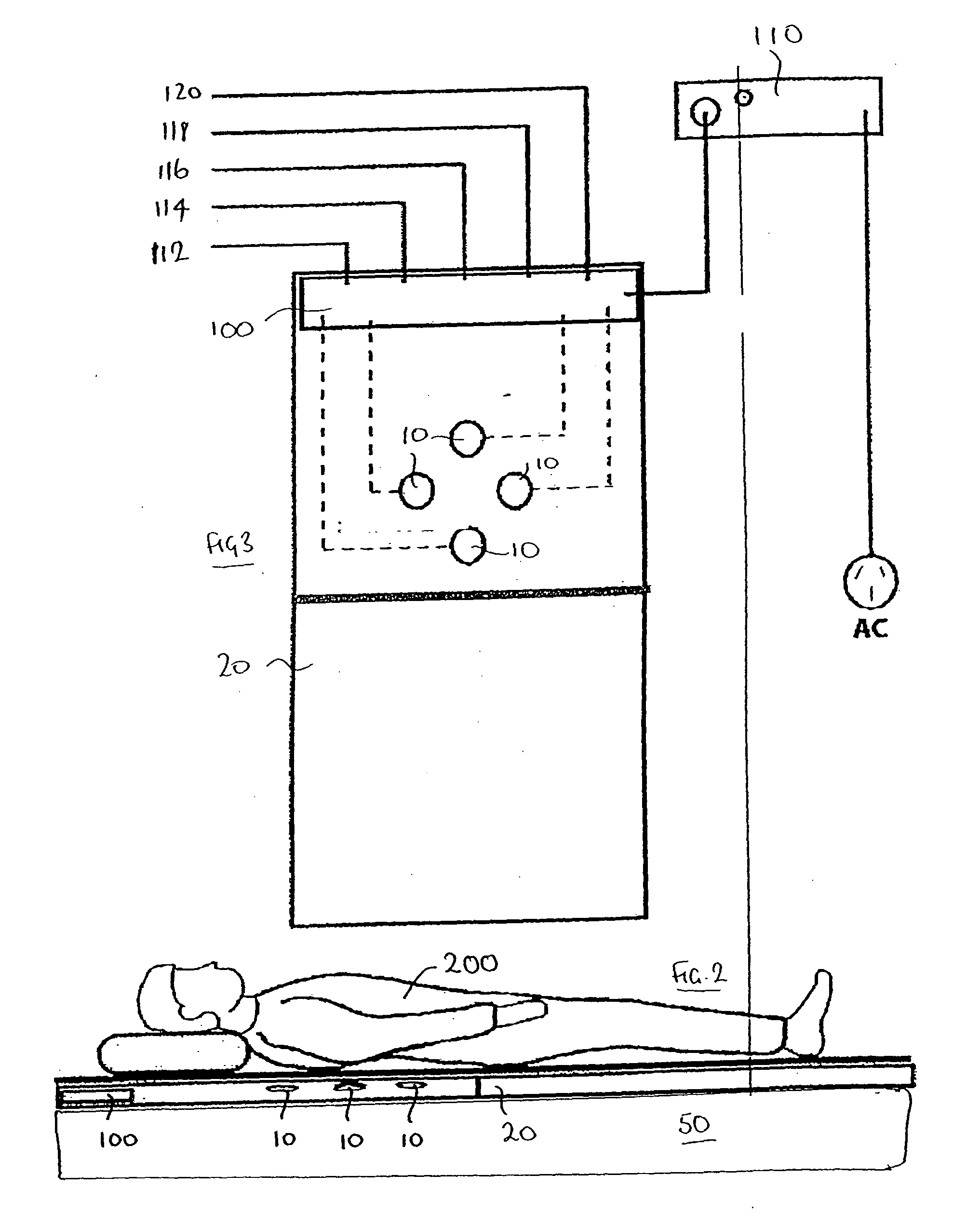
[0024]It is preferred that the mat comprises foam rubber and may typically be about 5 cm thick. The sensors may be mounted in holes formed in the foam rubber. Preferably biasing means are provided to bias the membrane / latex layer upwards in use against the patient. The mat is intended to the used in conjunction with a normal mattress as a mattress overlay. Thus, the underlying mattress acts to provide a support for a potentially wide range of body sizes, while the thin mat acts as a support and housing for the sensors. A particular advantage of housing the sensors in a mat is that the user does not have to position the individual sensors. The sensor array is such that the subject need only place the mat on a normal bed with the correct orientation), and the appropriate placement of the sensors is achieved as a result.
[0028]Preferably, the mat is rectangular and is sized to fit on top of a typical mattress. It has been found that having four sensors arranged in the second quarter of the mattress measured from the top edge / head arranged in a diamond formation ensures that at least one sensor is positioned against a patient's thorax to record breath sounds.

Problems solved by technology

However the problem with existing sensors is that they can be intrusive and have to be attached or pressed directly against a patient's chest wall or the like—as in the case of stethoscopes and ECG devices.
In the case of those sensors built into e.g. mattresses which a patient lies on, these do not always reliably pick up sounds such as breath sounds.
Also the sensors may make the mattress uncomfortable and disturb the patient's sleep.

Method used


Image

  • Sensor system
  • Sensor system
  • Sensor system

Examples


Embodiment Construction

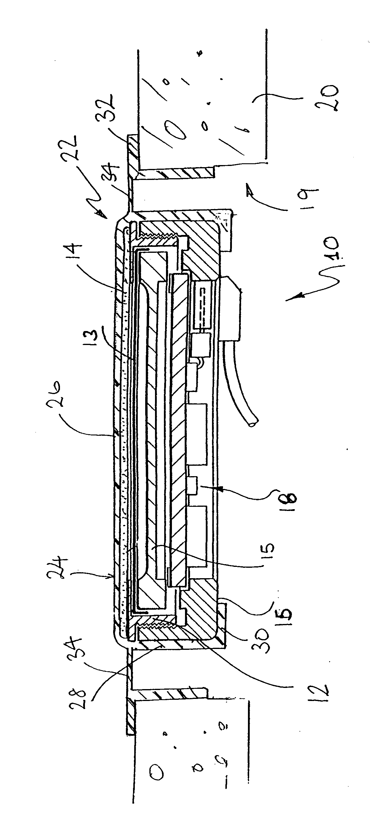
[0039]Referring to FIG. 1, an acoustic sensor 10 comprises a cylindrical aluminium body 12 having a sensor membrane in the form of a diaphragm of PVDF material 13 across its top. PVDF is a polymer with piezoelectric properties that it uses to generate electrical signals in response to acoustic and pressure vibration signals received. A thin 1-2 mm layer of an impedance matching material such as latex rubber 14 is located over the top of the sensor membrane 13.

[0040]The cylindrical body 12 extends at the top 15 to shield the diaphragm 13, and an aluminium ring 16 locks it in place and provides a live connector. Signals received at the sensor are analysed using built in circuitry mounted on a printed circuit board 18 to provide two or more electronic outputs. The outputs enable the recording and monitoring of signals of different frequency and, of particular significance, widely different amplitude, directly from a single sensor.

[0041]The complex signals generated from the patient may...


PUM


Abstract

A sensor system comprises a mat (20) for placement over a patient's mattress including a number of sensors (10) located in the mat. The sensors include a sensor housing (12), a sound vibration sensing element in the form of a PVDF membrane (13), and means for amplifying sensed sounds. The PVDF membrane is coated / covered with a typically latex, impedance matching layer (14). The sensor automatically provides for auscultation, in which the patient's own weight, from the patient lying on the bed, compresses their thorax against the membrane, compressing also the patient's clothing, bed sheet and mattress cover material between the two. The recoil in the mattress opposes the body mass, thus compressing the membrane against the thorax. The impedance matching layer on top of the membrane transmits fine breath sounds through to the membrane as the latex does not weaken or attenuate the fine breath sounds but transmits them to the PVDF membrane. However being flexible, it is not uncomfortable to lie on.

Description

CROSS-REFERENCE TO RELATED APPLICATIONS[0001]This application claims priority from Australian Provisional Patent Application No. 2007903117 entitled “Improved Sensor System” filed 8 Jun. 2007, the entire contents of which are incorporated herein by reference.FIELD OF THE INVENTION[0002]This invention relates to an improved sensor system and also to methods of diagnosis using the system.BACKGROUND OF THE INVENTION[0003]Many devices have been used and proposed for recording body movements, and breathing movements. One example is ECG measurements which require the application of ECG electrodes to a patients skin are able to provide “one off” diagnostic information, as well as being used over a period of time for patient monitoring.[0004]U.S. Pat. No. 5,989,193 (the entire contents of which are incorporated herein by reference) by the same inventor as the subject invention, discloses a device and method for detecting and recording the snoring of a patient. This device relies on pressure...

Claims


Application Information

Patent Timeline
IPC IPC(8): A61B5/08
CPCA61B5/113A61B5/6887G01H11/00A61G2203/36A61B7/003G01H11/08
Inventor SULLIVAN, COLIN EDWARD
Owner SONOMEDICAL
Learn More