Fuel cell module
a fuel cell and module technology, applied in the field of fuel cell modules, can solve problems such as heat absorption
- Summary
- Abstract
- Description
- Claims
- Application Information
AI Technical Summary
Benefits of technology
Problems solved by technology
Method used
Image
Examples
first embodiment
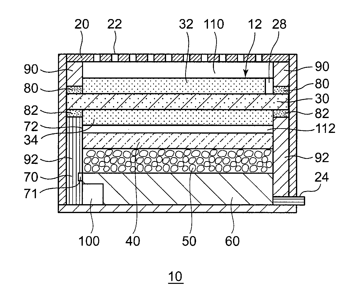
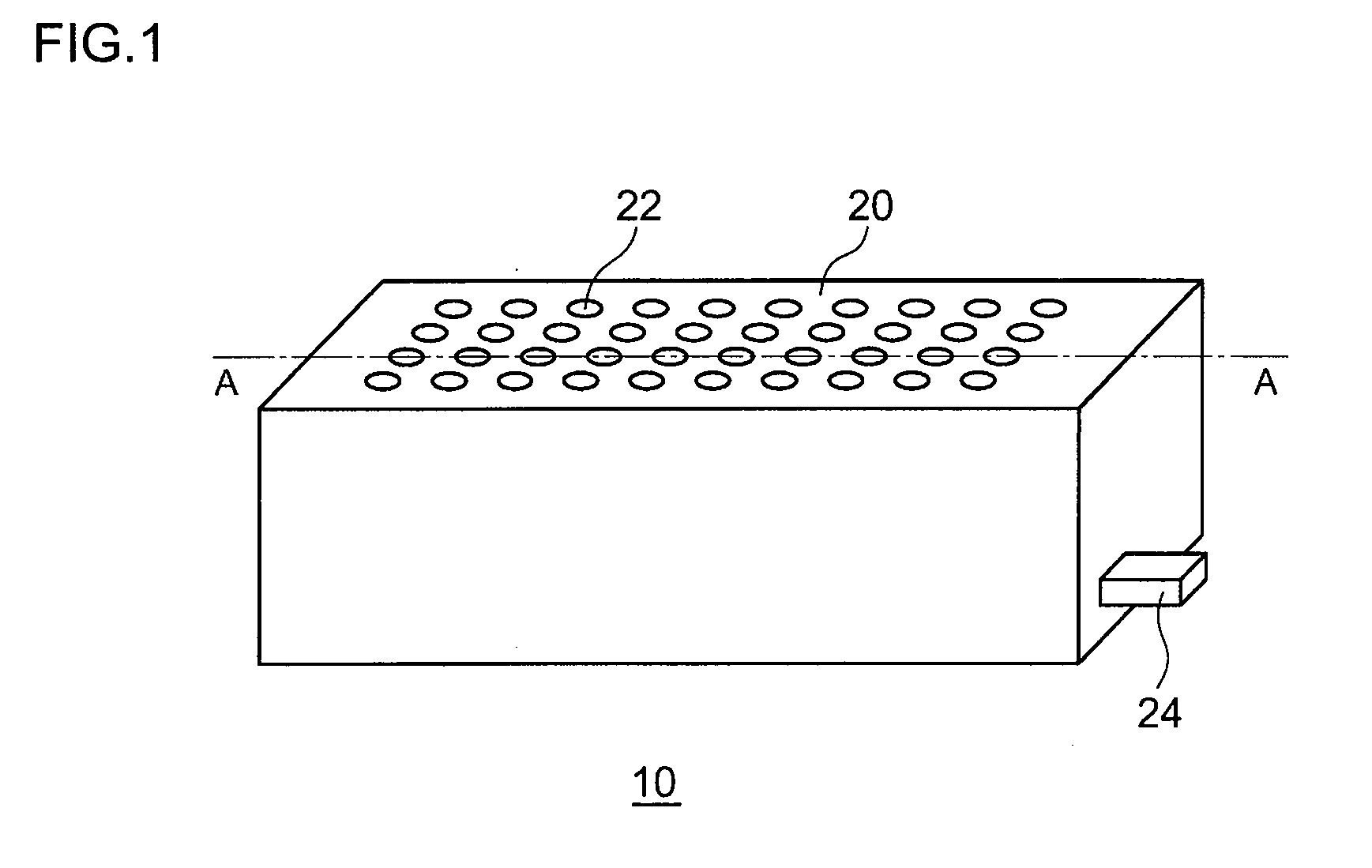
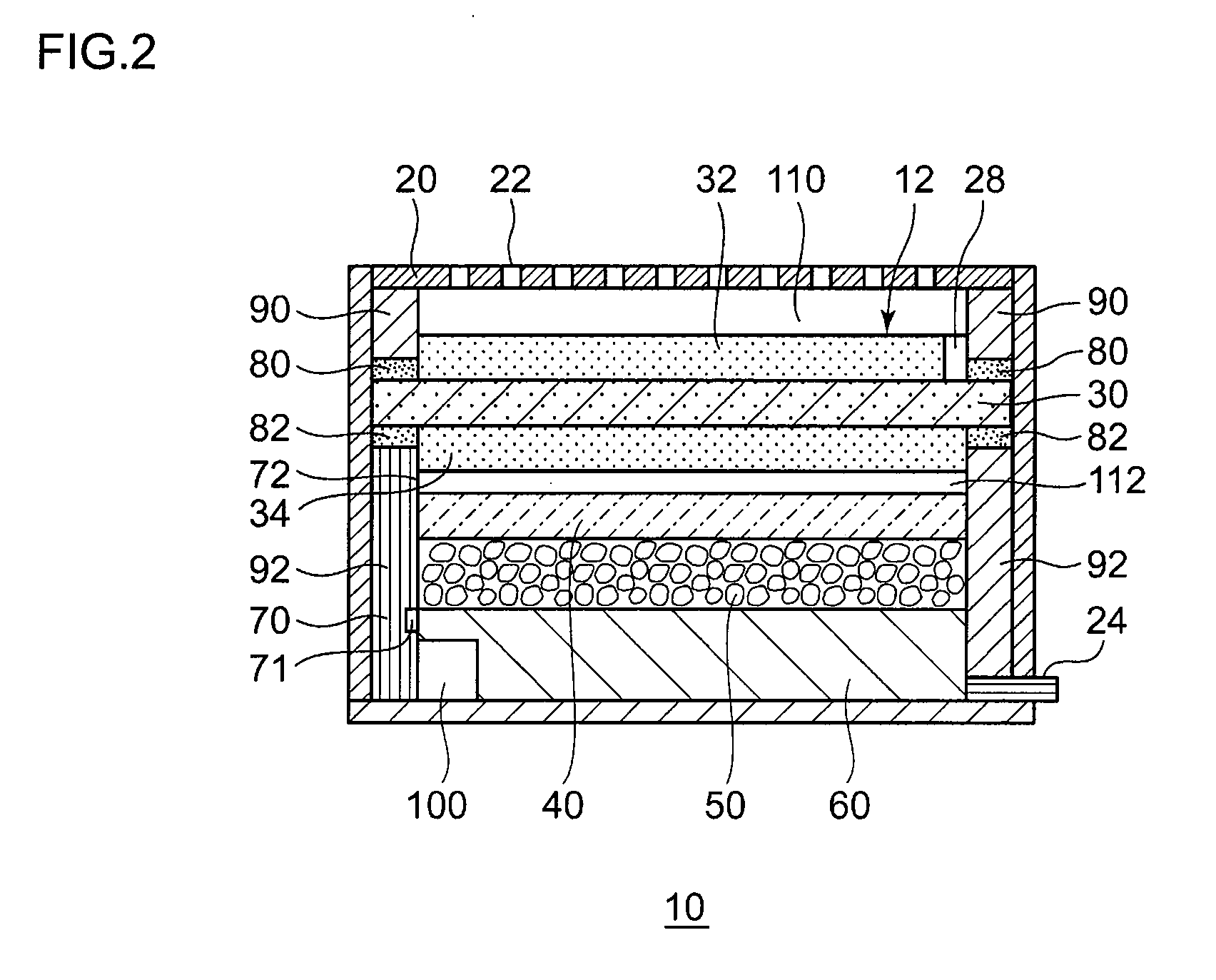
[0033]FIG. 1 is a perspective view showing the appearance of a fuel cell module according to a first embodiment of the present invention. FIG. 2 is a cross-sectional view taken along the line A-A of FIG. 1.
[0034]A fuel cell module 10 includes, as principal components, a housing 20, a membrane electrode assembly 12 housed in the housing 20, a hydrogen storage alloy tank 60, and a latent heat storage unit 50. Note that the membrane electrode assembly 12 is a part of the “fuel cell” or the “fuel cell” in its entirety described in this patent specification.
[0035]On a surface disposed opposite to a cathode side of the membrane electrode assembly 12 (the upper part in FIG. 1 and FIG. 2), the housing 20 is provided with a plurality of air inlets 22. Through the air inlets 2, air serving as an oxidant can flow into the housing 20 from outside.
[0036]In the vicinity of a side surface disposed opposite to the air inlets 22 (the lower part in FIG. 1 and FIG. 2), the housing 22 is also provided ...
second embodiment
[0077]FIG. 8 is a perspective view showing the appearance of a fuel cell module according to a second embodiment of the present invention. FIG. 9 is a cross-sectional view taken along the line A-A of FIG. 8. A fuel cell according to the second embodiment of the present invention is basically the same as that according to the first embodiment. Hence, a description of structural components of the fuel cell module according to the second embodiment identical to those of the fuel cell module according the first embodiment will be omitted as appropriate.
[0078]As shown in FIG. 8, in a fuel cell module 10 according to the second embodiment, a humidity sensor 26 is installed in the housing 20 near the air inlets 22. The humidity sensor 22 detects the humidity of environment where the housing 20 is placed. The humidity detected by the humidity sensor 26 is transmitted to the control unit 100.
[0079]FIG. 10 is a schematic illustration showing a structure of the latent heat storage unit 50 used...
third embodiment
[0088]FIG. 12 is a cross-sectional view of a fuel cell module according to a third embodiment of the present invention. FIG. 13 is a perspective view showing a structure of a latent heat storage unit used for a fuel cell module according to the third embodiment.
[0089]In the third embodiment, the latent heat storage unit 50, which is fixed within a heat-storage-material securing frame 200, is divided into three different regions (sections) which are a latent heat storage unit 50a, latent heat storage units 50b and latent heat storage units 50c. The heat-storage-material securing frame 200 is formed of a metallic material, a resin material or the like.
[0090]The latent heat storage unit 50a is provided in a region of the latent heat storage unit 50 corresponding to a middle region of the fuel cell module 10. The latent heat storage units 50b are provided around the latent heat storage unit 50a. The latent heat storage units 50c are provided around the latent heat storage units 50b. In ...
PUM
| Property | Measurement | Unit |
|---|---|---|
| thickness | aaaaa | aaaaa |
| thickness | aaaaa | aaaaa |
| size | aaaaa | aaaaa |
Abstract
Description
Claims
Application Information
 - R&D
- Intellectual Property
- Life Sciences
- Materials
- Tech Scout
- Unparalleled Data Quality
- Higher Quality Content
- 60% Fewer Hallucinations
Browse by: Latest US Patents, China's latest patents, Technical Efficacy Thesaurus, Application Domain, Technology Topic, Popular Technical Reports.
© 2025 PatSnap. All rights reserved.Legal|Privacy policy|Modern Slavery Act Transparency Statement|Sitemap|About US| Contact US: help@patsnap.com


