
Multi-link variable compression ratio engine

a variable compression ratio, multi-link technology, applied in the direction of connecting rods, shafts and bearings, bearings, etc., can solve the problem of more frequent knocking

Active Publication Date: 2009-04-30
NISSAN MOTOR CO LTD
View PDF8 Cites 132 Cited by
  • Summary
  • Abstract
  • Description
  • Claims
  • Application Information

AI Technical Summary

Benefits of technology

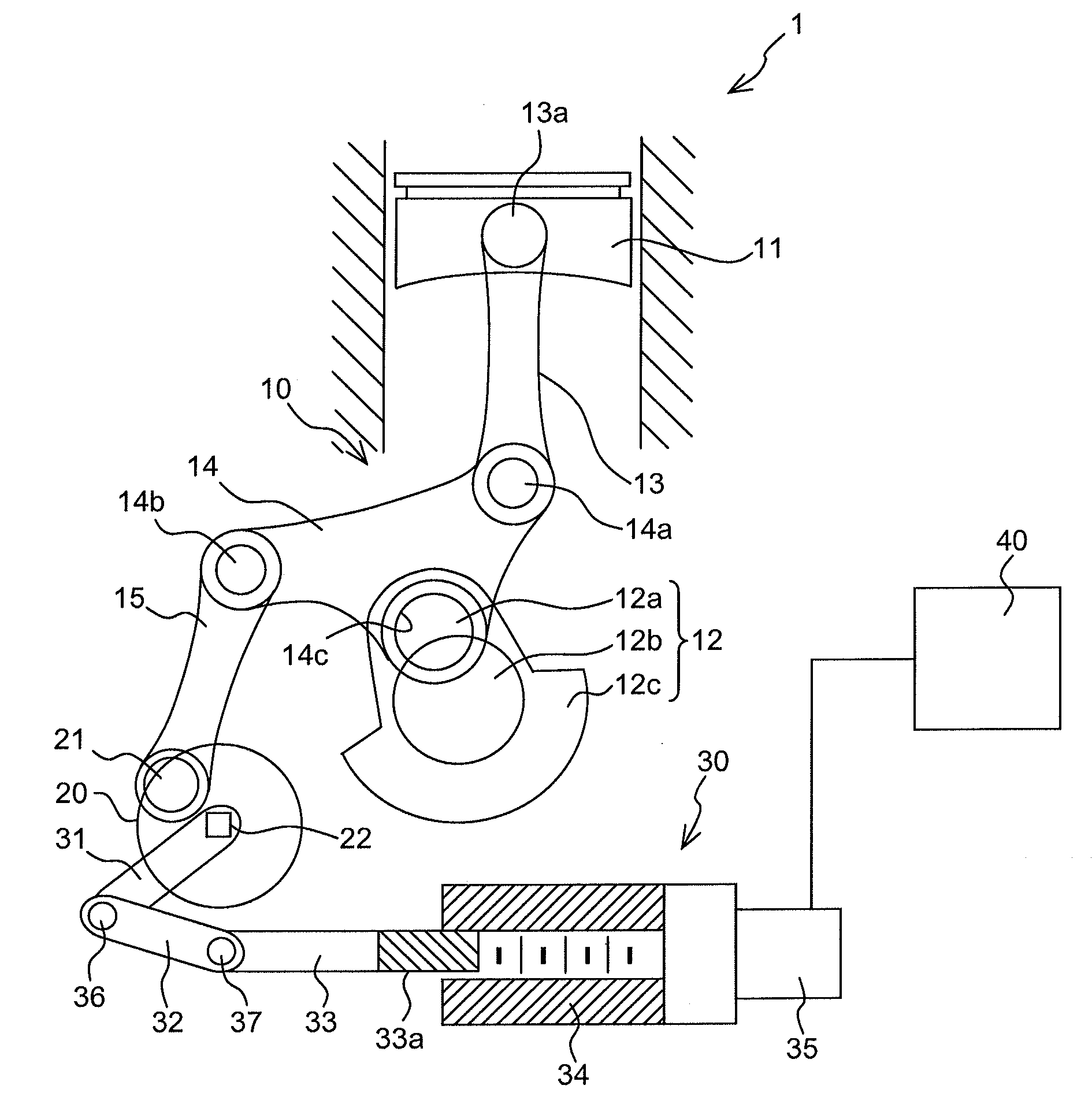
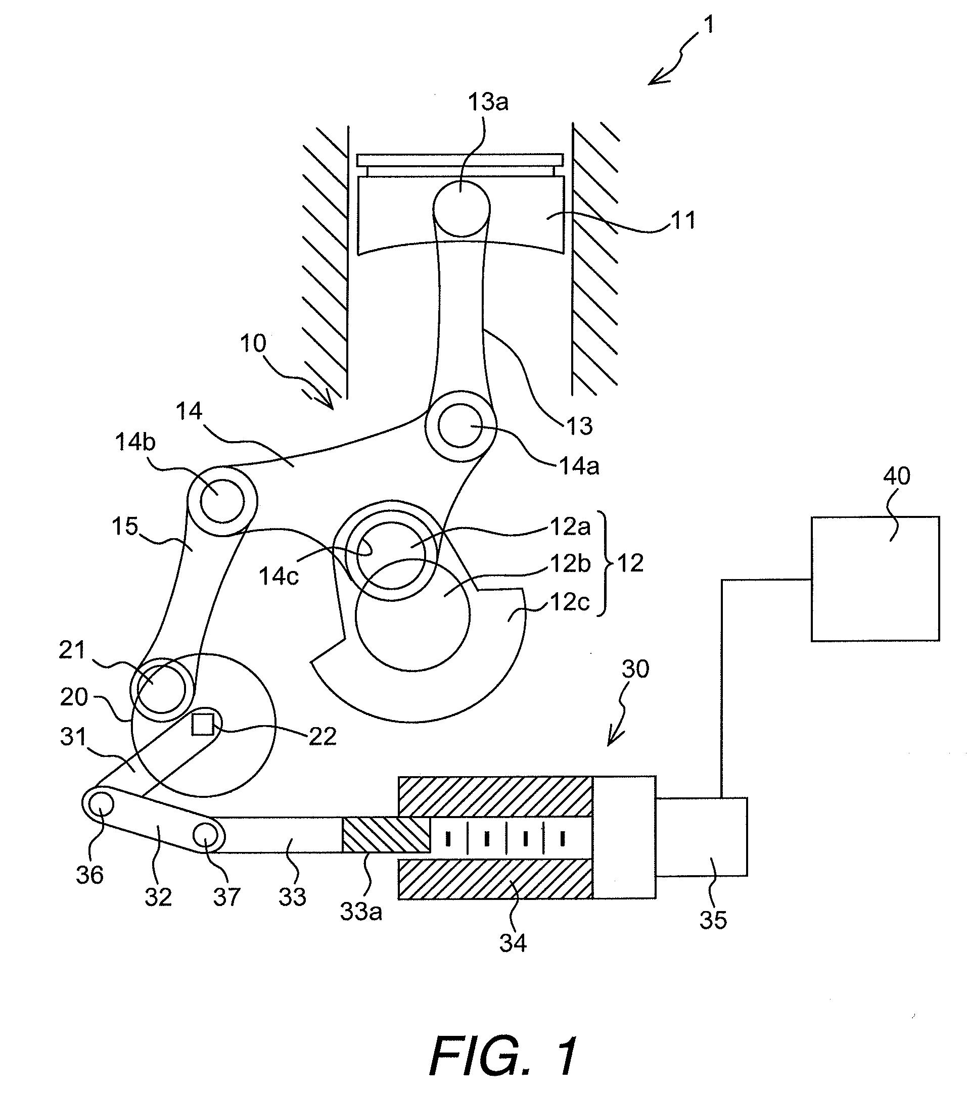
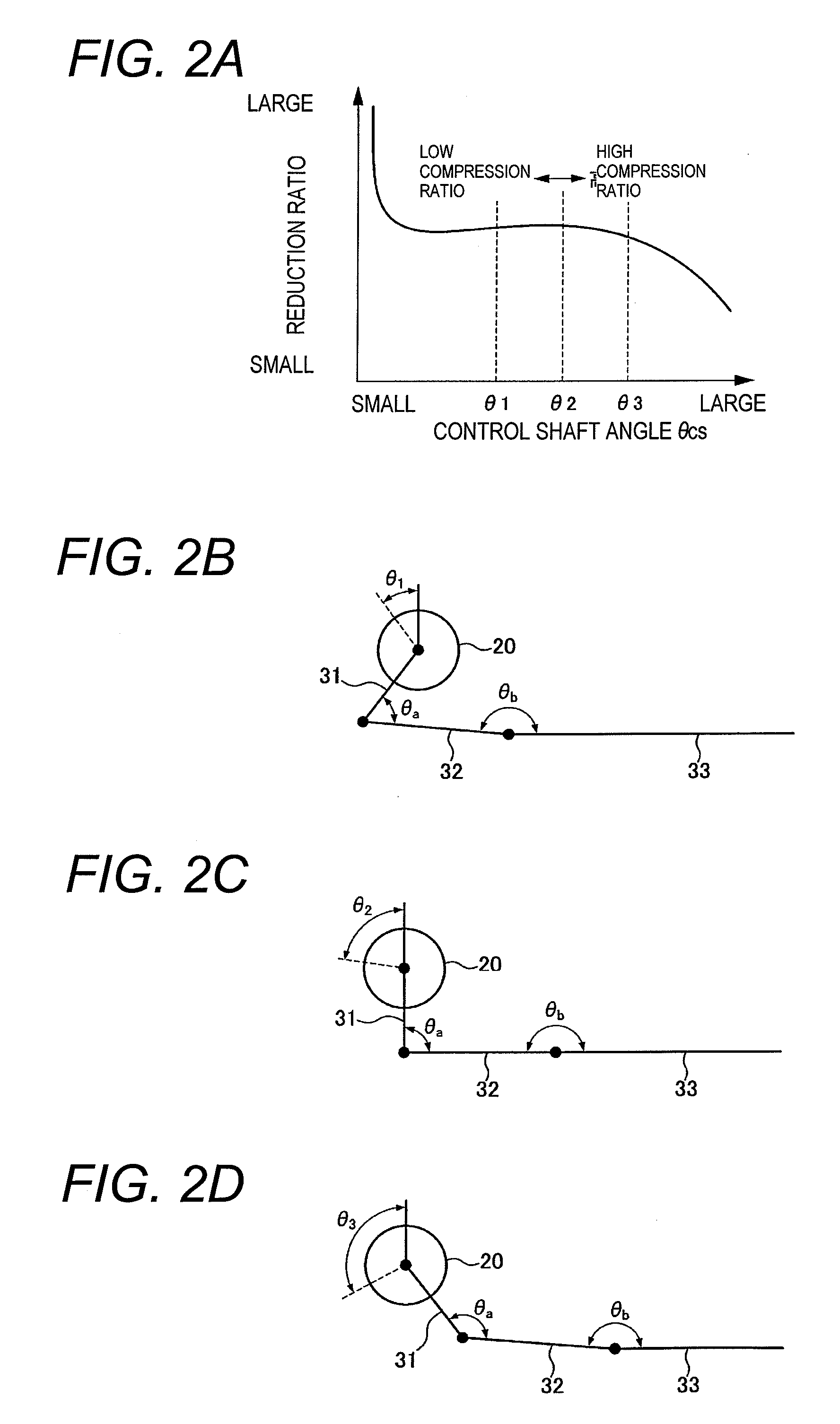
[0009]It has been discovered that in a conventional multi-link variable compression ratio engine, more frequent knocking occurs due to a slow change from a high compression ratio to an intermediate compression ratio.
[0010]In view of the problems described above, one object is to provide a multi-link variable compression ratio engine in which it is possible to suppress the occurrence of knocking caused by changes in the compression ratio.

Problems solved by technology

It has been discovered that in a conventional multi-link variable compression ratio engine, more frequent knocking occurs due to a slow change from a high compression ratio to an intermediate compression ratio.

Method used


Image

  • Multi-link variable compression ratio engine
  • Multi-link variable compression ratio engine
  • Multi-link variable compression ratio engine

Examples


second embodiment

[0071]Referring now to FIG. 5, a second embodiment of a reduction mechanism for the multi-link variable compression ratio engine 1 shown in FIG. 1 will now be explained. Basically, in this second embodiment, the control shaft 20 and the reduction mechanism 31-34 of the first embodiment are replaced in FIG. 1 with a modified structure as discussed below. In view of the similarity between the first and second embodiments, the descriptions of the parts of the second embodiment that are identical to the parts of the first embodiment may be omitted for the sake of brevity.

[0072]A shaft control mechanism 130 with a reduction mechanism for the multi-link variable compression ratio engine 1 shown in FIG. 1 will now be explained.

[0073]The essential configuration of the variable compression ratio engine 1 of the second embodiment is substantially the same as that of the first embodiment, but differs in the configuration of the shaft control mechanism 130. Namely, in the shaft control mechanis...


PUM


Abstract

A multi-link variable compression ratio engine is provided with a crankshaft, a piston, a control shaft, a linkage, a motor and a reduction mechanism. The crankshaft moves the piston within an engine cylinder. The control shaft has an eccentric axle eccentric relative to its center-axis. The linkage operatively connects the piston to the crankshaft and the crankshaft to the eccentric axle of the control shaft. The motor rotates the control shaft so a top-dead-center position of the piston changes to vary compression ratios by changing the positions of the eccentric axle and the linkage. The reduction mechanism couples the motor to the control shaft to transmit a reduced rotation of the motor to the control shaft so a reduction ratio of a rotation angle of the motor to a rotation angle of the control shaft is less at high-compression ratios than at intermediate compression ratios.

Description

CROSS-REFERENCE TO RELATED APPLICATIONS[0001]This application claims priority to Japanese Patent Application No. 2007-280370, filed on Oct. 29, 2007. The entire disclosure of Japanese Patent Application No. 2007-280370 is hereby incorporated herein by reference.BACKGROUND OF THE INVENTION[0002]1. Field of the Invention[0003]The present invention generally relates to a multi-link variable compression ratio engine. More specifically, the present invention relates to a variable compression ratio mechanism of an engine which uses, non-exclusively, a control shaft, multiple links, a drive motor, and a reduction mechanism to change a top dead center position of a piston.[0004]2. Background Information[0005]A known example of a variable compression ratio mechanism of an engine is one in which a piston and a crank are connected via a plurality of links. For example, in Japanese Laid-Open Patent Application No. 2005-163740, the piston and the crank are connected via an upper link and a lower...

Claims


Application Information

Patent Timeline
Patent Type & Authority Applications(United States)
IPC IPC(8): F02B75/32
CPCF02B75/048
Inventor HIYOSHI, RYOSUKETANAKA, YOSHIAKITAKEMURA, SHINICHI
Owner NISSAN MOTOR CO LTD
Learn More