Rechargeable battery
a rechargeable battery and battery technology, applied in the direction of wound/folded electrode electrodes, cell components, sustainable manufacturing/processing, etc., can solve the problems of low bonding strength between the current collecting plate and the electrode assembly, interrupting the battery's functioning, and undetected movement of the electrode assembly inside the case, etc., to achieve the effect of suppressing electrical resistan
- Summary
- Abstract
- Description
- Claims
- Application Information
AI Technical Summary
Benefits of technology
Problems solved by technology
Method used
Image
Examples
first embodiment
[0058]Hereinafter, other embodiments and variations will be described. Repeated description of parts that are similar to or the same as those of the first embodiment will be omitted.
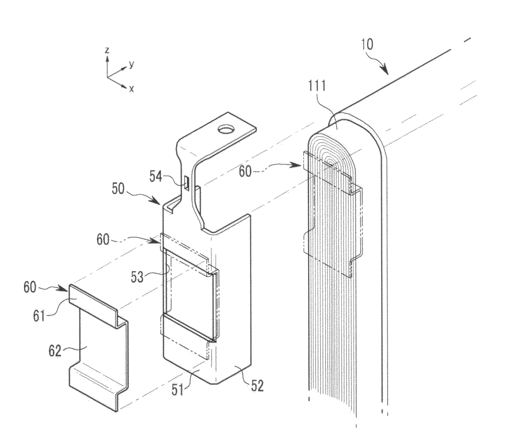
[0059]FIG. 4 illustrates an exploded perspective view of a lead member 50, a current collecting plate 260 and an electrode assembly 10 of a rechargeable battery according to a second embodiment. FIG. 5 illustrates a cross-sectional view of FIG. 4, taken along the line V-V thereof. Referring to FIG. 4 and FIG. 5, the current collecting plate 260 may be disposed on an uncoated region 211 with increased pressure, compared to that of the current collecting plate 60 of the first embodiment disposed in the uncoated region 111 in a static condition. That is, a second connection portion 262 of the current collecting plate 260 may have an elastic force that presses the current collecting plate 260 toward an end of the uncoated region 211.
second embodiment
[0060]As shown in FIG. 4, prior to assembly, the current collecting plate 260 of the second embodiment may maintain a separated state (dotted line) from the uncoated region 211 along the y-axis in a lead member 50. As shown in FIG. 4, when the lead member 50 is coupled to the uncoated region 211, the lead member 50 may surround part of the uncoated region 211. The current collecting plate 260 may contact the uncoated region 211. In this case, the second connection portion 262 of the current collecting plate 260 may be electrically connected to the uncoated region 211, while deforming and pressing the uncoated region 211. Elastic force exerted by the current collecting plate 260 may increase bonding strength of a welding point between the current collecting plate 260 and the uncoated region 211, and may suppress an increase of electrical resistance at the welding point.
[0061]The current collecting plate 260 may further include an indentation portion 263 in the second connection porti...
fourth embodiment
[0066]Referring to FIG. 7, a current collecting plate 460 of the fourth embodiment may include a first connection portion 461, a second connection portion 462 and a plurality of indentation portions 463. The first and second connection portions 461 and 462 may be substantially parallel to each other. The indentation portions 463 may be bent relative to the second connection portion 462. Each indentation portion 463 may be formed as a triangular structure of which a side opposite to an uncoated region 411 may be opened at a cross-section of the yz plane in the penetration hole 53 of the lead member 50. Each indentation portion 463 may have a pointed end pointing in the y-axis direction so that a welding area with the uncoated region 411 may be small compared to the third exemplary embodiment, but may easily indent the uncoated region 411.
PUM
| Property | Measurement | Unit |
|---|---|---|
| thickness | aaaaa | aaaaa |
| pressure | aaaaa | aaaaa |
| shape | aaaaa | aaaaa |
Abstract
Description
Claims
Application Information
 - R&D
- Intellectual Property
- Life Sciences
- Materials
- Tech Scout
- Unparalleled Data Quality
- Higher Quality Content
- 60% Fewer Hallucinations
Browse by: Latest US Patents, China's latest patents, Technical Efficacy Thesaurus, Application Domain, Technology Topic, Popular Technical Reports.
© 2025 PatSnap. All rights reserved.Legal|Privacy policy|Modern Slavery Act Transparency Statement|Sitemap|About US| Contact US: help@patsnap.com


