
Backlight and displaying/imaging apparatus

Active Publication Date: 2010-09-30
JAPAN DISPLAY WEST
View PDF5 Cites 9 Cited by
  • Summary
  • Abstract
  • Description
  • Claims
  • Application Information

AI Technical Summary

Benefits of technology

[0006]It is therefore desirable to provide a backlight capable of suppressing loss of light from an invisible light source and a displaying / imaging apparatus using the same.
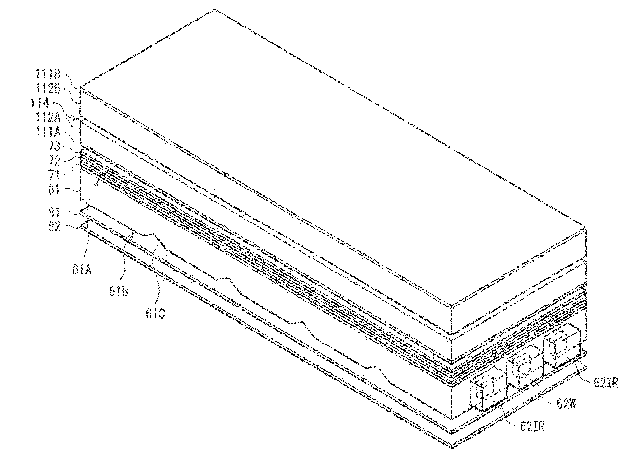
[0014]In the backlight of an embodiment of the invention, on the rear face side of the light guide plate, the first reflection film reflecting the light from the visible light source and transmitting the light from the invisible light source, and the second reflection film reflecting the light from at least the invisible light source out of the visible light source and the invisible light source are provided. Therefore, even in the case where the light from the invisible light source goes out on the rear face side of the light guide plate, it is reflected by the second reflection film and enters again on the rear face of the light guide plate. Consequently, even in the case where light from the invisible light source passes through the first reflection film, loss of the light from the invisible light source is suppressed. On the other hand, light from the visible light source is reflected by the first reflection film and enters on the rear face of the light guide plate.
[0015]Since the displaying / imaging apparatus of an embodiment of the invention has the backlight of an embodiment of the invention, loss of invisible light in the backlight is suppressed. Therefore, power consumption is reduced.
[0016]According to the backlight of an embodiment of the invention, on the rear face side of the light guide plate, the first reflection film reflecting the light from the visible light source and transmitting the light from the invisible light source, and the second reflection film reflecting the light from at least the invisible light source out of the visible light source and the invisible light source are provided, so that loss of the light from the invisible light source is suppressed. Therefore, when a displaying / imaging apparatus is constructed by using the backlight, reduction in power consumption is realized.

Problems solved by technology

However, in a common backlight, optical members such as a light guide plate, a reflection film, and a lens film are formed so as to extract white light efficiently in the surface of the light guide plate, and there is a case that excellent characteristics are not obtained with respect to invisible light.
For example, since the reflectance of invisible light in a reflection film is extremely low, the invisible light passes through without being reflected, and loss is large.

Method used


Image

  • Backlight and displaying/imaging apparatus
  • Backlight and displaying/imaging apparatus
  • Backlight and displaying/imaging apparatus

Examples


embodiment

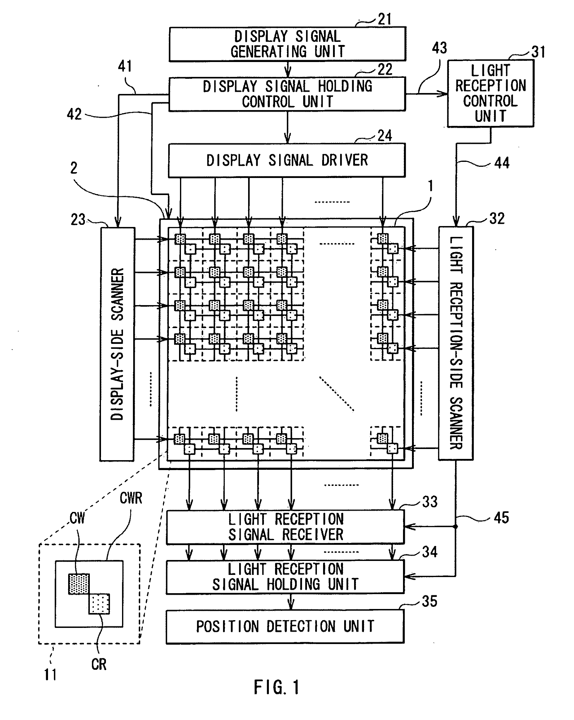
[0031]FIG. 1 illustrates a schematic configuration of a displaying / imaging apparatus according to an embodiment of the present invention. The displaying / imaging apparatus is used for a medium-size or large-size display apparatus such as a liquid crystal television or a mobile device such as a cellular phone or a game machine. The displaying / imaging apparatus has, for example, an input / output panel 1 and a backlight 2. The displaying / imaging apparatus has a display signal generating unit 21, a display signal holding control unit 22, a display-side scanner 23, a display signal driver 24, a light reception control unit 31, a light reception-side scanner 32, a light reception signal receiver 33, a light reception signal holding unit 34, and a position detecting unit 35.

[0032]In the entire input / output panel 1, a plurality of pixels 11 are disposed in a matrix, and an image of a predetermined figure, a character, or the like is displayed while performing line-sequential operation. Each p...


PUM


Abstract

The present invention provides a backlight capable of suppressing loss of light from an invisible light source and a displaying / imaging apparatus using the same. The backlight includes: a light guide plate having a light emitting face and a rear face opposed to the light emitting face; a visible light source disposed on a side face of the light guide plate; an invisible light source disposed on a side face of the light guide plate; a first reflection film disposed on the rear face side of the light guide plate, reflecting light from the visible light source, and transmitting light from the invisible light source; and a second reflection film disposed on the rear face side of the light guide plate and reflecting light from at least the invisible light source out of the visible light source and the invisible light source.

Description

BACKGROUND OF THE INVENTION[0001]1. Field of the Invention[0002]The present invention relates to a backlight and a displaying / imaging apparatus having the same.[0003]2. Description of the Related Art[0004]There is a displaying / imaging apparatus in which a display cell including one display element and a light receiving cell including one light receiving element are formed in a part of a liquid-crystal or organic-EL display device or in each pixel to enable light receiving operation together with display operation to be performed (see, for example, Japanese Unexamined Patent Application Publication No. 2006-127212). The light receiving cell is an optical sensor circuit including a photoelectric conversion element such as a photodiode as a light receiving element, and a TFT (Thin Film Transistor) as a switching element. In such a displaying / imaging apparatus, information as output of the light receiving cell is used for input or space position detection.SUMMARY OF THE INVENTION[0005]I...

Claims


Application Information

Patent Timeline
IPC IPC(8): F21V7/04
CPCG02B6/0055G02B6/0068G02F2001/13312G09G2360/18G09G2320/0626G09G2360/148G09G3/3426G02F1/13312
Inventor YANG, YING BAOSUZUKI, TAKAFUMIKIMURA, SUSUMUHIGUCHI, MASARUKONDOH, MASAKI
Owner JAPAN DISPLAY WEST
Learn More