System and method for compensating instability in an autofocus system

a technology of autofocus and stability, applied in the field of autofocus system, can solve the problems of affecting the reliability of the measured height of the substrate, the inability to achieve environmental control to a certain level,

Inactive Publication Date: 2010-09-30
NIKON CORP
View PDF32 Cites 13 Cited by
  • Summary
  • Abstract
  • Description
  • Claims
  • Application Information

AI Technical Summary

Benefits of technology

[0004]In a known autofocus (AF) system, e.g. of the slit detection type, broadband illumination is used to illuminate a set of sending slits that are projected onto the surface of the substrate at glancing angle of incidence. A vibrating mirror is used to translate the slit image(s) across a small portion of the substrate. Another image of the slit(s) is incident on a set of receiving slits with the same basic geometry as the sending slits (size, orientation, etc) to create a time varying signal that is related to the height of the substrate relative to the AF system. The set of slits imaged on the substrate are used in combination with moving the substrate past the AF system, and allows the height of the entire substrate surface to be mapped.
[0010]In essence, with the present invention, an autofocus determination is produced by mapping the z position of the substrate relative to the reflector for the reference beam, which produces information that enables compensation for instabilities in the system components and / or environmental factors. The information enables autofocus compensation in the form of a direct compensation of the measured height of the substrate, or in the form of a signal that identifies the likelihood that there are instabilities in the system that may be affecting the reliability of the measured substrate height, so that the source of such instabilities may be investigated.
[0014]In addition, the present invention also provides ways of compensating for factors such as index differences, index gradients, and changes in index gradient with time, particularly in the first and second air spaces, which could otherwise affect the autofocus determination. For example, to adjust for index differences in the non common first and second air spaces, the present invention directs a dedicated air supply to the non common first and second air spaces. To adjust for index gradients in the non common first and second air spaces, the reference and measurement beams that emerge from the beam splitting optic are directed through one or more slits and detected by means of slit detectors, and the geometry of the sending and detecting slits can be changed to reduce or remove the sensitivity to index gradients in the non common first and second air spaces. To adjust for changes in index gradients with time in the first and second non common air spaces, the present invention provides adjusting the size, shape and orientation of the detection slits.

Problems solved by technology

Environmental control can only be achieved to a certain level.
In addition, instabilities in the mechanical components of an autofocus system, e.g. the vibrating mirrors, optics, etc., may also affect the reliability of the measured height of the substrate.

Method used


Image

  • System and method for compensating instability in an autofocus system
  • System and method for compensating instability in an autofocus system
  • System and method for compensating instability in an autofocus system

Examples


Embodiment Construction

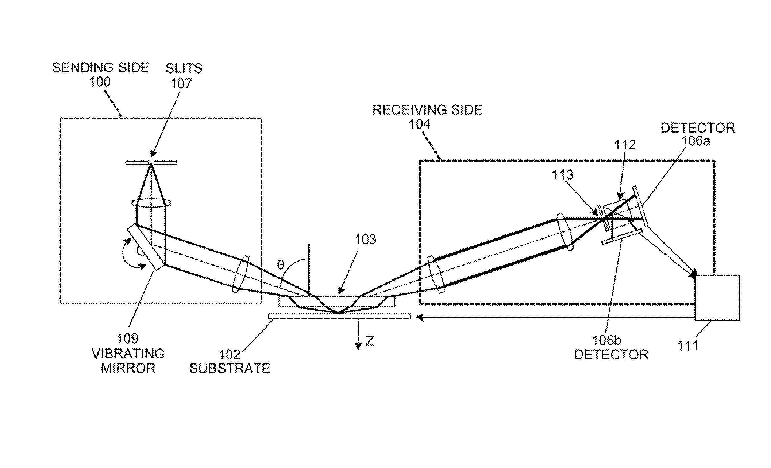
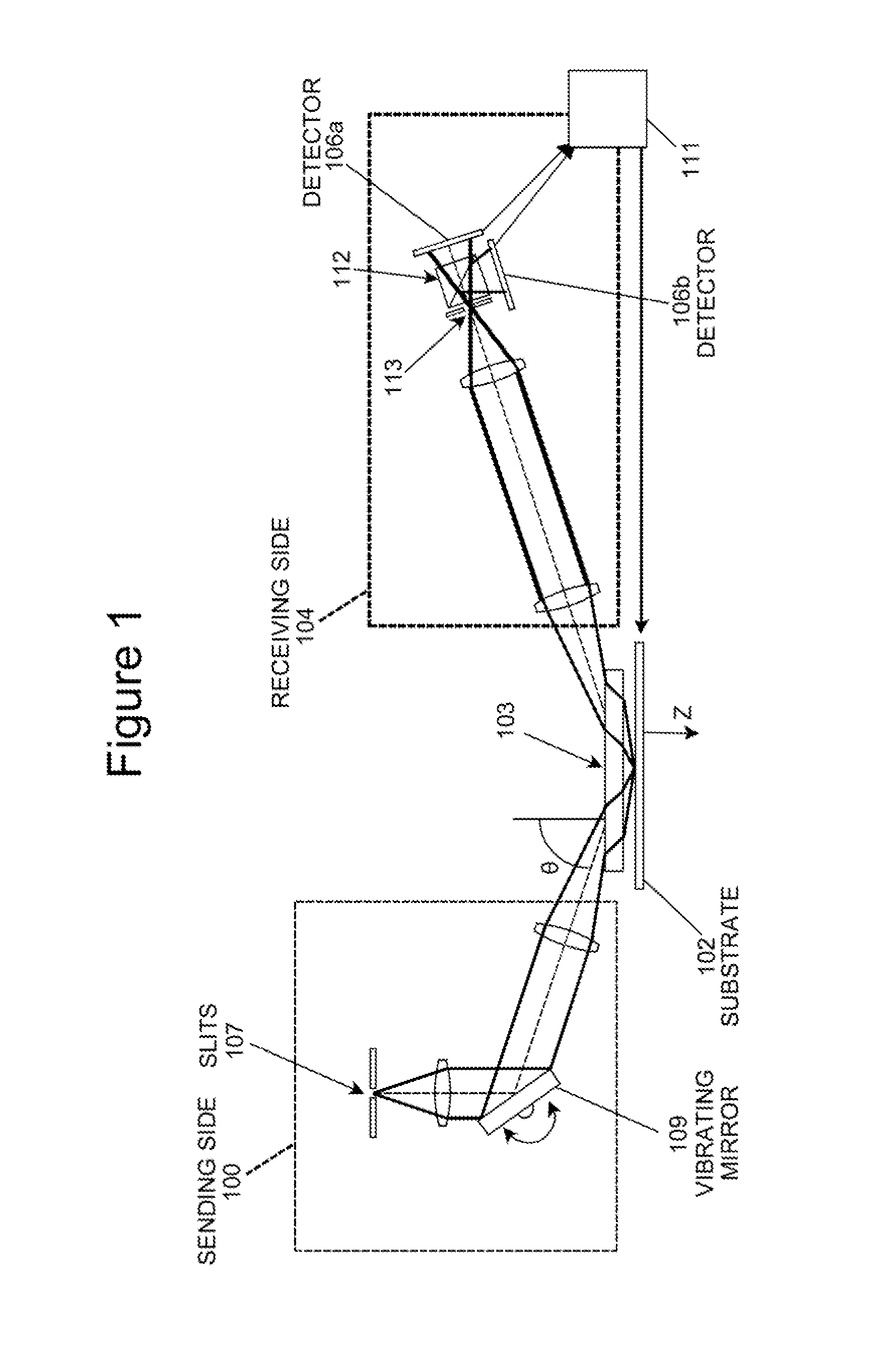
[0027]As described above, the principles of the present invention are particularly useful in an autofocus system and method of the slit detection type. The principles of the present invention are described herein in connection with a system and method of the slit detection type, and from that description the manner in which the principles of the present invention can be applied to other types of autofocus systems and methods (e.g. of the fringe detection type shown in U.S. provisional patent application Ser. No. 61 / 244,321 filed Sep. 21, 2009 and entitled “Goos-Hanchen compensation in auto-focus system by optimal spectrum or digital spectral filter”, which is incorporated by reference herein for all purposes) will be apparent to those in the art. Also, while a slit type autofocus system and method generally provides autofocus beams that emerge from a plurality of slits and are directed through corresponding slits associated with slit detectors, the principles of the invention are de...


PUM


Abstract

An autofocus system and method designed to account for instabilities in the system, e.g. due to instabilities of system components (e.g. vibrating mirrors, optics, etc) and / or environmental effects such as refractive index changes of air due to temperature, atmospheric pressure, or humidity gradients, is provided. An autofocus beam is split into a reference beam component (the split off reference channel) and a measurement beam component, by a beam splitting optic located a predetermined distance from (and in predetermined orientation relative to) the substrate, to create a first space between the beam splitting optic and the substrate. A reflector is provided that is spaced from the beam splitting optic by the predetermined distance, to create a second space between the reflector and the beam splitting optic. The measurement beam component is directed at the substrate and a reflected measurement beam component through the first space between the substrate and the beam splitting optic, while the reference beam component is directed at the reflector and a reflected reference beam component is directed from the reflector through the second space between the beam splitting optic and the reflector. The reflected reference and measurement beam components are returned to the beam splitting optic, and emerge substantially collinear from the beam splitting optic. The reference and measurement beam components are then detected, and provide information that enables compensation for changes in the z position of the substrate that are due to instabilities in the autofocus system components and / or environmental factors.

Description

RELATED APPLICATION / CLAIM OF PRIORITY[0001]This application is related to and claims priority from provisional application Ser. No. 61 / 165,426, filed Mar. 31, 2009, which provisional application is incorporated by reference herein.INTRODUCTION[0002]The present invention provides an autofocus system and method designed to compensate for instabilities in the system, e.g. due to instabilities of system components (e.g. vibrating mirrors, optics, etc) and / or environmental effects such as refractive index changes of air due to temperature, atmospheric pressure, or humidity changes or gradients, any or all of which may affect the reliability of the autofocus output when an autofocus beam is directed at and reflected from a substrate.[0003]Generally, in an autofocus system and method, an autofocus beam is directed at a substrate (e.g. in the manufacture of a semi conductor substrate), at an angle of incidence designed to enable the topography of the surface of the substrate to be determine...

Claims


Application Information

Patent Timeline
IPC IPC(8): G01N21/55G02B27/14G02B15/14
CPCG02B27/40G02B7/28G01B11/02
Inventor GOODWIN, ERIC PETERSMITH, DANIEL GENESOGARD, MICHAEL
Owner NIKON CORP
Why Eureka
Try Eureka