Eureka AIR delivers breakthrough ideas for toughest innovation challenges, trusted by R&D personnel around the world.

Energy harvesting system

a technology of energy harvesting and energy harvesting, which is applied in the direction of liquid based dampers, machine/engines, home appliance efficiency improvement, etc., can solve the problem of electric energy to be generated

Inactive Publication Date: 2010-09-30
BHAT NIKHIL +1
View PDF51 Cites 48 Cited by
  • Summary
  • Abstract
  • Description
  • Claims
  • Application Information

AI Technical Summary

Benefits of technology

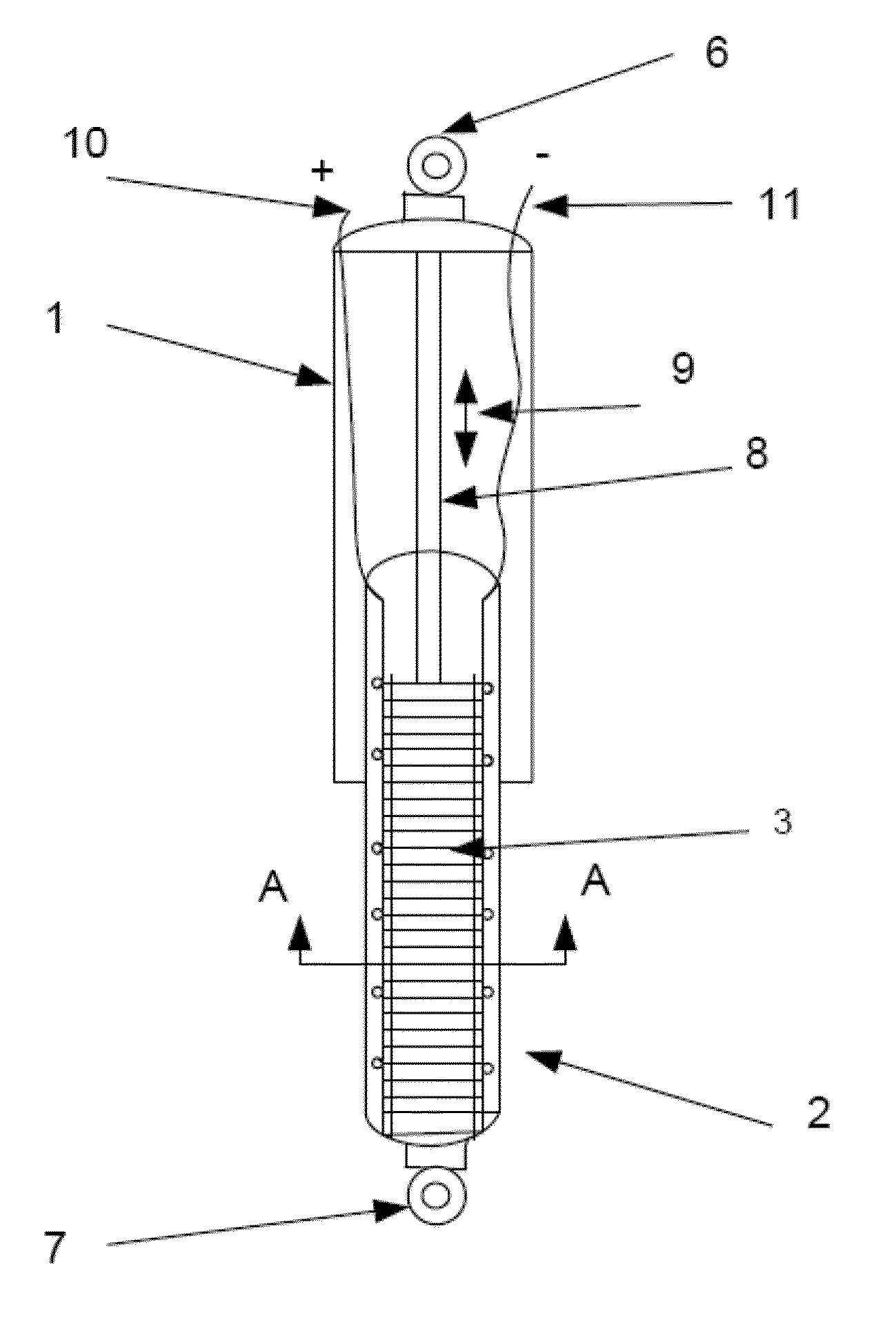
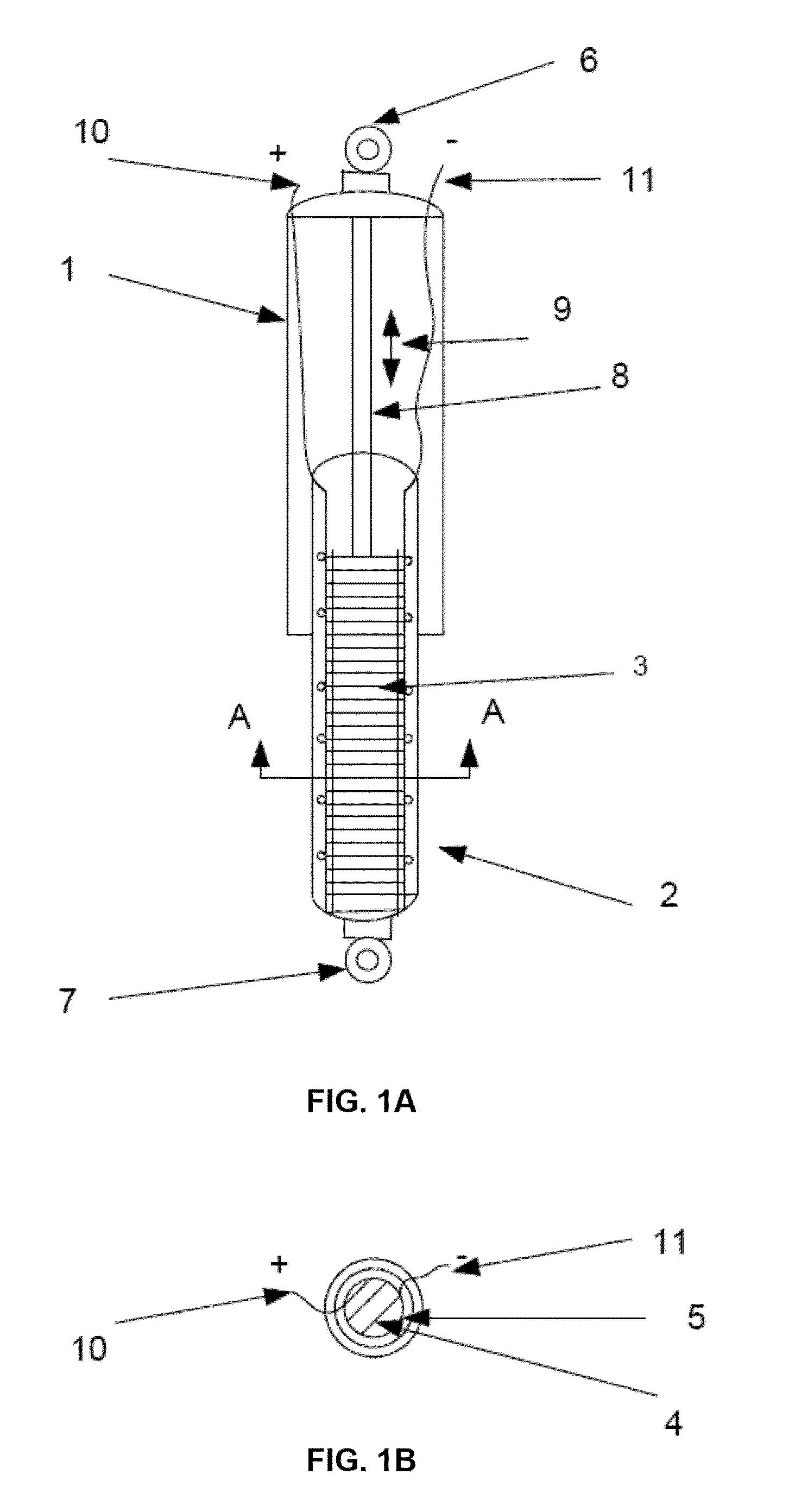
[0012]Another example of the shock absorber may comprise at least two chambers which move relative to each other such that a piston attached to one of the chambers may translate (e.g., move up and down) in the second chamber. A fixed volume of viscous fluid such as oil or water may be disposed in the second chamber. The walls of the chamber may be lined by layers of the electroactive polymer material, e.g., dielectric elastomer, hence creating a compliant housing. This shock absorber may be connected in the vehicle such that when the vehicle is moving the mechanical vibrations generated in response to bumps, road surface irregularities, and other projections cause the piston to move up and down. This oscillatory and linear movement of the piston may pressurize and de-pressurize the fixed volume of the viscous fluid present in the chamber such that the oscillatory change in the pressure causes the compliant housing to expand and contract / relax cyclically which in turn causes the electroactive polymer material to stretch and contract / relax cyclically and generate useful electrical energy for harvesting and / or storing.
[0013]In another example, a shock absorber having at least two chambers which may move relative to each other may utilize a piston attached to one of the chambers which may move (e.g., up and down) in the second chamber. The piston may be comprised of a fixed non-compressible rod which is connected to a first generator element. The first generator element may in-turn be connected to a second generator element with a biasing element, such as a compression spring. Each following generator element may be connected to the adjacent previous one with a biasing element such as a compression spring. The numbers of generator elements can range from one or more depending on the size of the generators and also the energy requirements. As the vehicle moves, the generated vibrations causes the piston to move, e.g., up and down, such that the biasing elements may compress and expand. The biasing elements may amplify some of the vibration signals which in turn causes each generator element to stretch and compress in a controlled manner and controlled stretching and compression of the generator element causes the generation of useful electrical energy.
[0016]In another example, the dielectric elastomer generators may be used as an energy generating engine mount which has a housing assembly containing layers of dielectric elastomer material. This material may be stacked one above the other in a first chamber and with the remaining chamber filled with a viscous fluid, such as oil or water, under pressure. An impermeable elastic membrane may separate the layers of electroactive polymers from the fluid region. A cover with a central opening may be placed on top of the housing with a piston of a plunger passed through the opening and sealed against the opening with seals such that the piston is able to move up and down relative to the housing assembly. The piston may have a disc type distal end with the diameter of the disc equal to or slightly less than the internal diameter of the housing. The proximal end of the piston or plunger may have a connector which couples the engine mount to the vibrating engine. The housing assembly may have a connector which also couples the housing to the vehicle. Under operation of the vehicle, as the engine starts vibrating the vibrations are converted into linear oscillatory vertical motions which are transmitted to the plunger assembly. This forces the plunger to moves up and down causing the fluid to be pressurized and de pressurized. This change in the fluid pressure may effectively cause the electroactive polymer material to stretch and compress leading to the generation of useful electrical energy.

Problems solved by technology

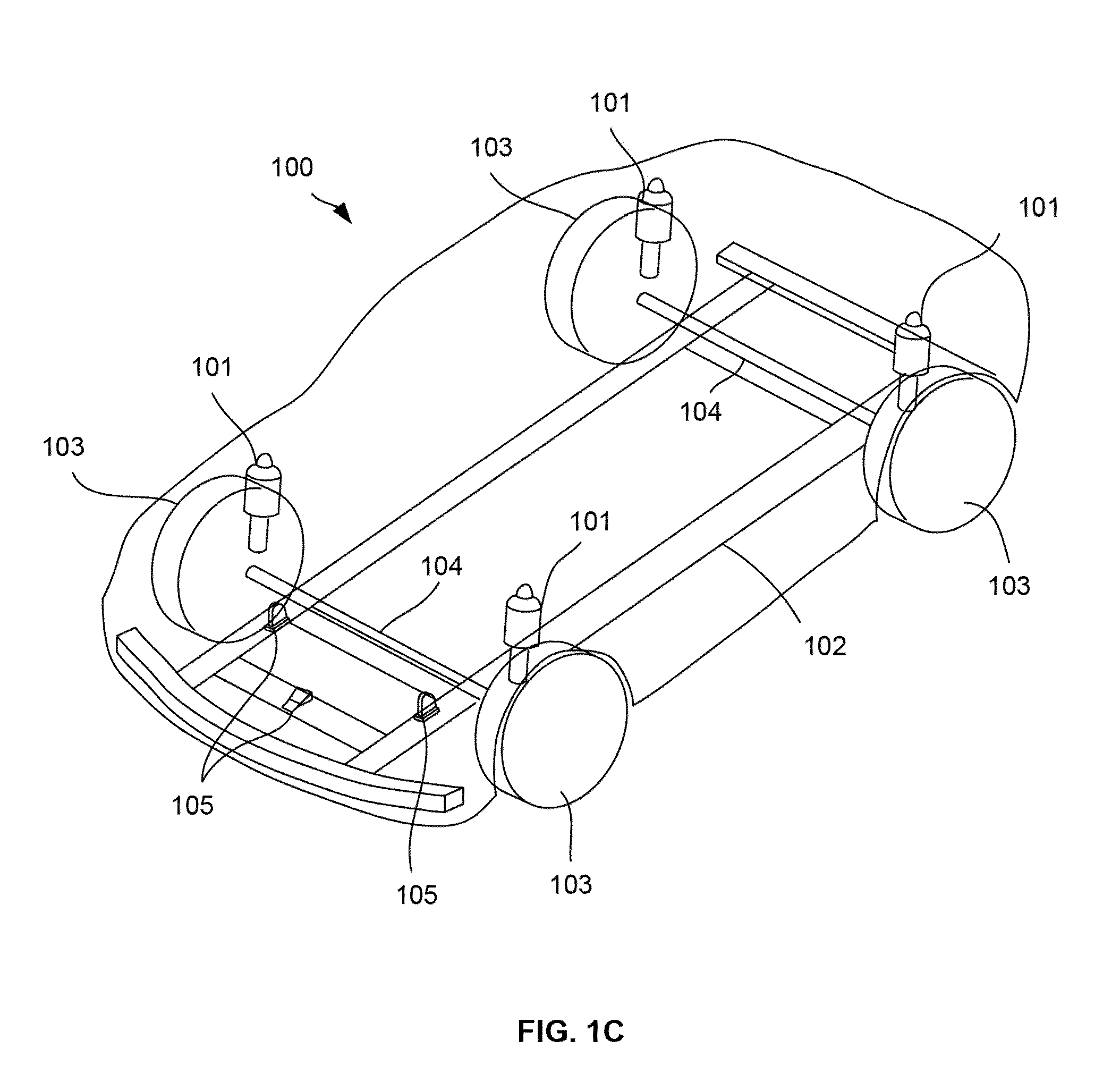
As the vehicle travels, the translational movement (e.g., up and down motion) generated by the vehicle may causes a plunger connected to one of the chambers to move against or upon the stacked dielectric elastomer generators which may cause stretching and contracting / relaxing of the dielectric elastomer which in turn causes electrical energy to be generated.

Method used


Image

  • Energy harvesting system
  • Energy harvesting system
  • Energy harvesting system

Examples


Embodiment Construction

[0029]Improving vehicle energy efficiency is desirable with hybrid and electrical vehicle technology more commonplace. With road surfaces uneven and full of bumps, one method for improving vehicle efficiency is by capturing energy which is normally lost through heat, noise, vibrations, etc., as vehicles travel over these roads. The average bump height along an average road can vary from 2 mm to 6 mm while the frequency of the bumps can vary from 1 / 10 to 1 / 100 cm−1.

[0030]Dielectric elastomers, which are a type of electroactive polymers, may be used to capture and convert these vibrations from, e.g., the wheels, engine, seats, etc., for energy generation as the vehicle is in use. The types of engines may vary from internal combustion to electric engines or any other type of engine which may be used by any type of vehicle. Generally, dielectric elastomer generators comprise soft stretchable polymer materials such as acrylic, silicone rubber, polyurethane, etc., which may be placed betw...


PUM


Abstract

Energy harvesting systems are described in which electroactive materials, such as dielectric elastomers, may be utilized to absorb the shocks, bumps, and vibrations from the road or path to generate energy which is captured and stored for use in the vehicle to provide additional power for any number of uses. Other devices and systems, such as household appliances which dissipate vibrational energy, may also incorporate any number of the dielectric elastomer generators.

Description

CROSS-REFERENCE TO RELATED APPLICATIONS[0001]This application claims the benefit of priority to U.S. Prov. App. 61 / 163,344 filed Mar. 25, 2009, which is incorporated herein by reference in its entirety.FIELD OF THE INVENTION[0002]The present invention relates to systems and methods for harvesting energy from any vehicle, particularly automobiles and any other vibrating industrial and household appliance. More particularly, the present invention relates to systems and methods for harvesting energy from the suspension or shock absorbing system of the vehicle.BACKGROUND OF THE INVENTION[0003]Vehicle suspension systems give passengers a comfortable ride typically by supporting the vehicle and responding to road bumps, road irregularities by moving up and down. But these motions induce undue oscillations or vibrations and a damper or shock absorber is used to dampen out the vibrations. Typical shock absorbers function by dissipating or absorbing the unwanted energy.[0004]There are severa...

Claims


Application Information

Patent Timeline
IPC IPC(8): F03G7/08H02N2/18H01L41/113
CPCB60G13/14Y02B40/54B60G2202/42B60G2300/60B60K25/10F16F9/19F16F15/005H01L41/083H02N2/186F03B13/14F03D9/002Y02E10/38Y02B10/30Y02B10/70D06F39/006D06F37/20B60G2202/20F03G7/08Y02B40/00Y02E10/30Y02B10/50H10N30/50D06F39/20
Inventor BHAT, NIKHILCHOI, GEORGE YOSEUNG
Owner BHAT NIKHIL
Why Eureka
Eureka Blog
Learn More