
Element interconnection member, photoelectric conversion element and a series of photoelectric conversion elements including the same, and photoelectric conversion module

a technology of photoelectric conversion elements and interconnection members, which is applied in the direction of printed circuit details, power plants, semiconductor devices, etc., can solve the problems of poor contact, disadvantageous assembly, and inability to ensure the contact of an interconnection pattern to all electrodes to be connected, etc., and achieve poor electrical connection and poor electrical connection

Inactive Publication Date: 2010-09-30
SHARP KK
View PDF11 Cites 28 Cited by
  • Summary
  • Abstract
  • Description
  • Claims
  • Application Information

AI Technical Summary

Benefits of technology

[0014]The present invention was made to solve the above-described problems, and one object of the present invention is to provide an element interconnection member improving poor connection to an electrode by relaxing stress involved with connection to an electrode formed on a photoelectric conversion element and achieving a higher degree of freedom in arranging electrodes. Another object is to provide a photoelectric conversion element to which such an element interconnection member is connected. Yet another object is to provide a series of photoelectric conversion elements obtained by connecting a plurality of photoelectric conversion elements to one another through the element interconnection members. Still another object is to provide a photoelectric conversion module including such a series of photoelectric conversion elements.Means for Solving the Problems
[0035]A photoelectric conversion module according to the present invention includes the series of photoelectric conversion elements above. Therefore, as described above, stress involved with heat shrinkage can be released in this photoelectric conversion module and poor electrical connection between each connection portion and the first electrode or the second electrode can be improved.

Problems solved by technology

Therefore, registration accuracy of an interconnection substrate with respect to a cell substrate is required in order to avoid electrical short-circuiting due to contact of an interconnection pattern with an electrode to which it should basically not be connected, and assembly disadvantageously becomes complicated.
In addition, since an interconnection pattern is formed on a surface of an interconnection substrate, contact of an interconnection pattern to all electrodes to be connected has not been ensured and poor contact has sometimes occurred.

Method used


Image

  • Element interconnection member, photoelectric conversion element and a series of photoelectric conversion elements including the same, and photoelectric conversion module
  • Element interconnection member, photoelectric conversion element and a series of photoelectric conversion elements including the same, and photoelectric conversion module
  • Element interconnection member, photoelectric conversion element and a series of photoelectric conversion elements including the same, and photoelectric conversion module

Examples


first embodiment

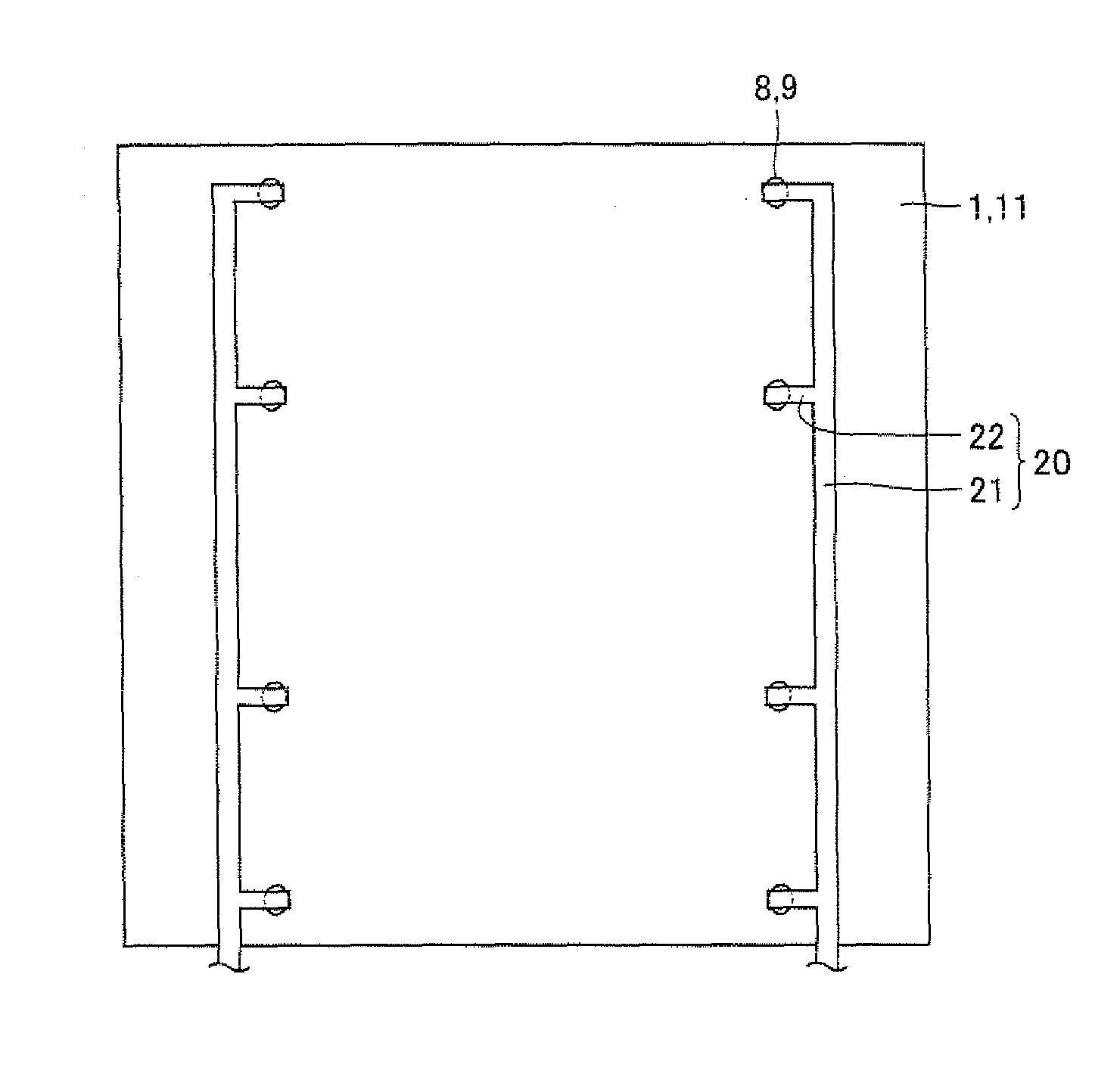
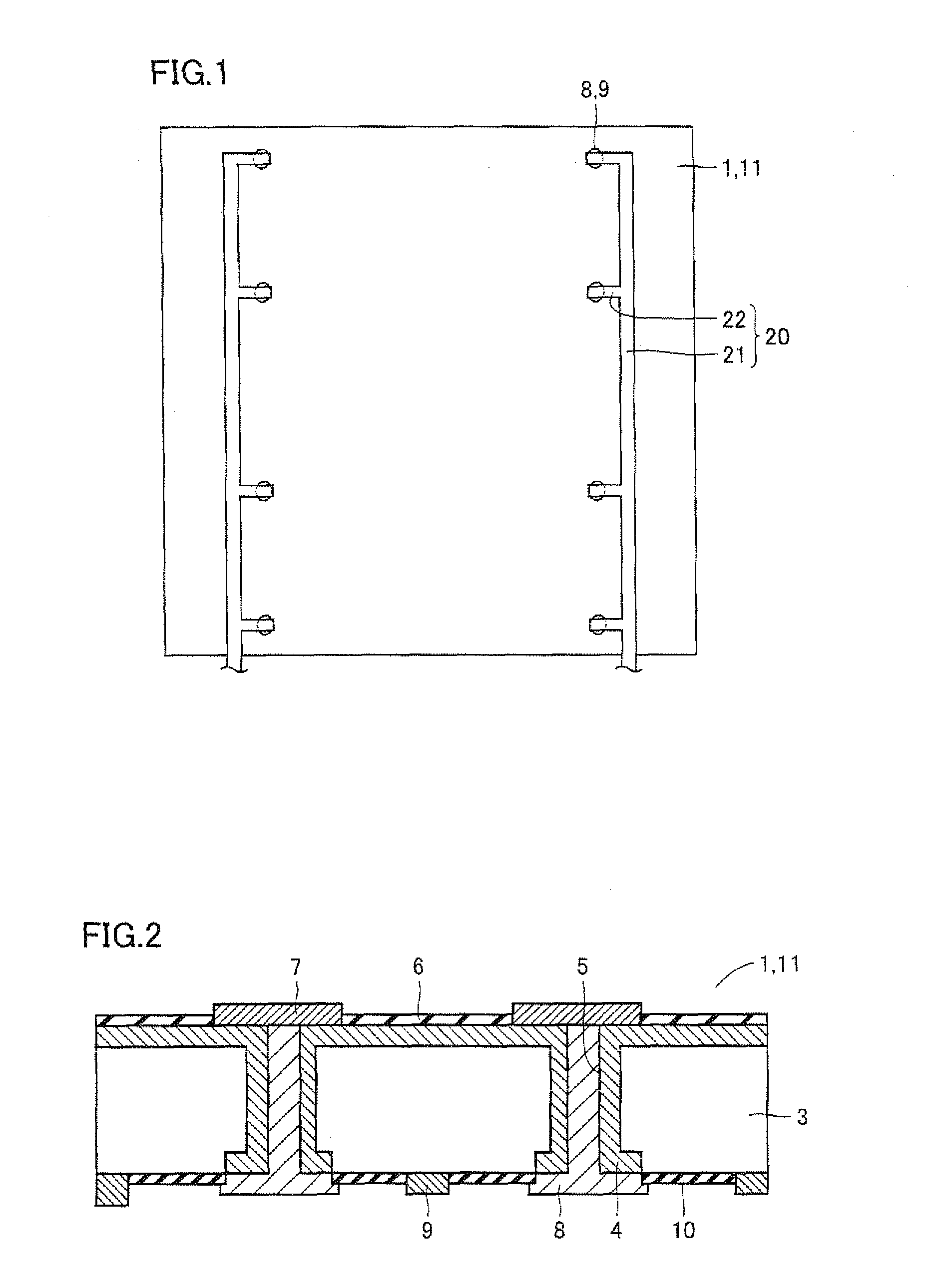
[0083]Initially, a basic structure of an interconnector (an element interconnection member) according to an embodiment of the present invention will be described. As shown in FIG. 1, an interconnector 20 includes an extending portion 21 extending in one direction and a connection portion 22 fixed to an n electrode 8 or a p electrode 9 formed on a cell substrate (a photoelectric conversion substrate) 11 of a photoelectric conversion element 1 for connection to these electrodes 8, 9. This one direction is based on a direction in which cell substrates 11 are arranged or a direction in which electrodes 8 and 9 are arranged. Connection portion 22 is formed in a comb shape so as to protrude from extending portion 21 in a direction substantially orthogonal to that one direction. Though extending portion 21 comes in contact with cell substrate 11, it is not fixed to cell substrate 11.

[0084]As will be described later, by not fixing extending portion 21 of interconnector 20 to cell substrate ...

second embodiment

[0144]Here, a photoelectric conversion module including the series of photoelectric conversion elements described previously will be described, As shown in FIG. 45, in a photoelectric conversion module 30, the series of photoelectric conversion elements 12 is sealed with a sealing material 32 composed of EVA (Ethylene Vinyl Acetate) resin. Sealing material 32 sealing the series of photoelectric conversion elements 12 is sandwiched between a glass plate 33 serving as a surface protection layer and a back film 31. One external terminal 35a and the other external terminal 35b of the series of photoelectric conversion elements 12 are taken out of back film 31. In addition, a frame 34 formed of an aluminum frame is attached to surround glass plate 33, sealing material 32 and back film 31 from an outer side.

[0145]An exemplary method of manufacturing photoelectric conversion module 30 will now briefly be described. Initially, the series of photoelectric conversion elements 12 is sandwiched...


PUM


Abstract

An interconnector includes an extending portion extending in one direction and a connection portion fixed to an n electrode or a p electrode formed on a cell substrate of a photoelectric conversion element for connection to this electrode. The connection portion is formed in a comb shape so as to protrude from the extending portion in a direction substantially orthogonal to the one direction. Though the extending portion is in contact with the cell substrate, it is not fixed to the cell substrate. By not fixing the extending portion to the cell substrate, stress involved with heat shrinkage can be released and a degree of freedom in arrangement of the n electrode and the p electrode formed on the photoelectric conversion element can be enhanced.

Description

TECHNICAL FIELD[0001]The present invention relates to an element interconnection member, a photoelectric conversion element and a series of photoelectric conversion elements including the same, as well as a photoelectric conversion module, and particularly to an element interconnection member connecting element-formed substrates to one another each having a prescribed element main body formed thereon, a photoelectric conversion element in which such an element interconnection member is connected to an element-formed substrate, a series of photoelectric conversion elements obtained by electrically connecting a plurality of photoelectric conversion element substrates to one another through a plurality of element interconnection members, and a photoelectric conversion module including such a series of photoelectric conversion elements.BACKGROUND ART[0002]Solar cells having electrodes on opposing surfaces are dominant among currently mass-produced solar cells. In a solar cell having ele...

Claims


Application Information

Patent Timeline
IPC IPC(8): H01L31/042H05K1/11H01L31/00
CPCH01L31/02245H01L31/0236Y02E10/50H01L31/0516H01L31/18H01L31/0508
Inventor SAINOO, YASUSHIOKAMOTO, SATOSHI
Owner SHARP KK
Learn More