
Approach for determining exhaust gas sensor degradation

a technology for exhaust gas sensors and degradation, applied in the direction of machines/engines, vehicle components, process and machine control, etc., can solve the problems of increasing emissions, reducing vehicle drivability, and reducing engine control based likelihood, so as to reduce the impact on vehicle drivability and/or emissions, and improve the accuracy of exhaust gas sensor degradation determination

Active Publication Date: 2010-09-30
FORD GLOBAL TECH LLC
View PDF11 Cites 29 Cited by
  • Summary
  • Abstract
  • Description
  • Claims
  • Application Information

AI Technical Summary

Benefits of technology

The patent describes a method for detecting degradation of an exhaust gas sensor in a vehicle and using this information to control engine operation to reduce emissions and improve vehicle drivability. The method involves modulating the air / fuel ratio of the engine and monitoring the response of the exhaust gas sensor to determine if degradation is present. By identifying the specific types of degradation behavior, the accuracy of determining exhaust gas sensor degradation is improved and a simple method for monitoring degradation is provided. This allows for timely adjustments to engine control to minimize the impact on vehicle performance and emissions.

Problems solved by technology

Degradation of an exhaust gas sensor may cause engine control degradation that may result in increased emissions and / or reduced vehicle drivability.
Accordingly, accurate determination of exhaust gas sensor degradation may reduce the likelihood of engine control based on readings from a degraded exhaust gas senor.

Method used


Image

  • Approach for determining exhaust gas sensor degradation
  • Approach for determining exhaust gas sensor degradation
  • Approach for determining exhaust gas sensor degradation

Examples


Embodiment Construction

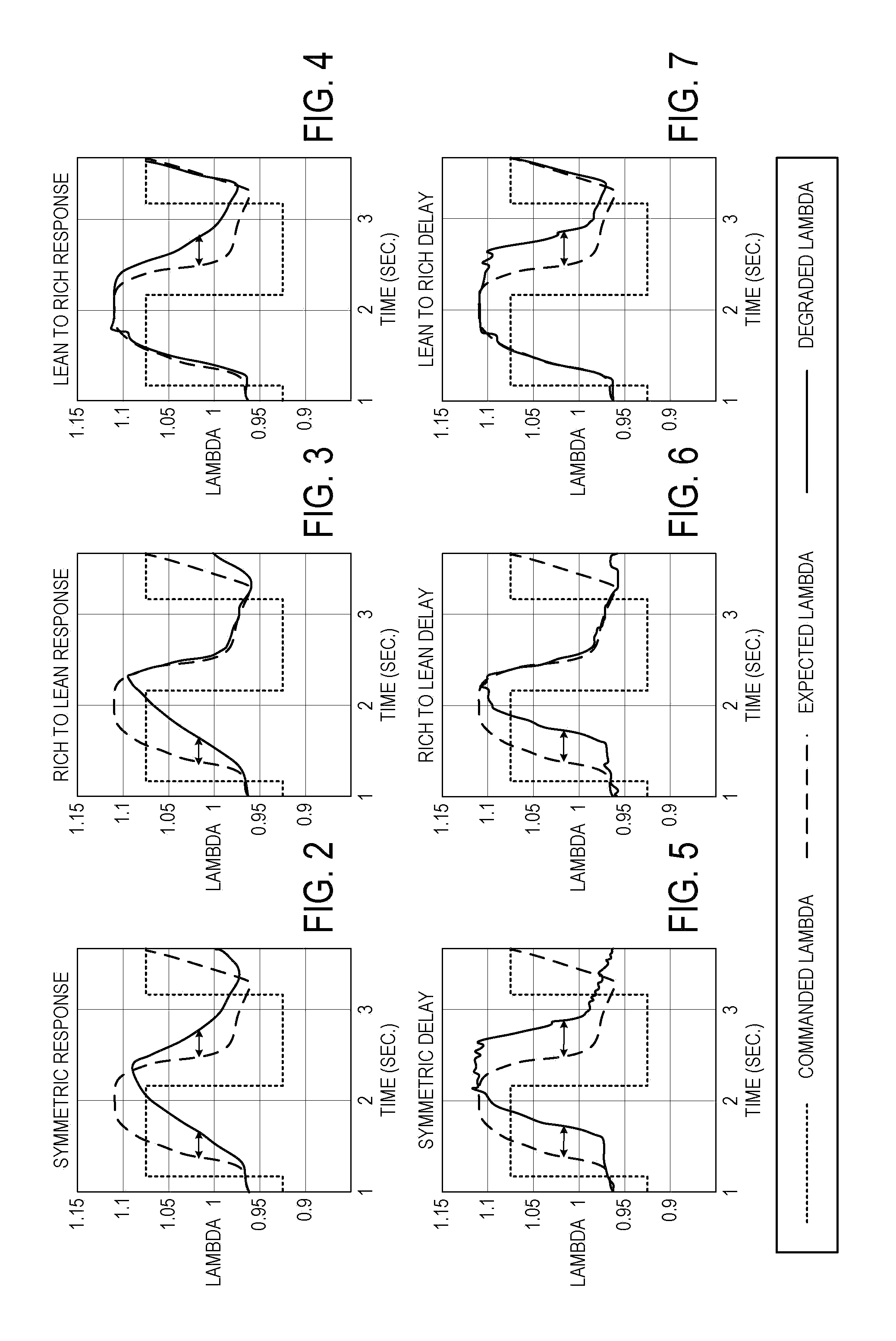
[0014]The following description relates to an approach for determining degradation of an exhaust gas sensor. More particularly, the systems and methods described below may be implemented to determine exhaust gas sensor degradation based on recognition of any one of six discreet types of behavior associated with exhaust gas sensor degradation.

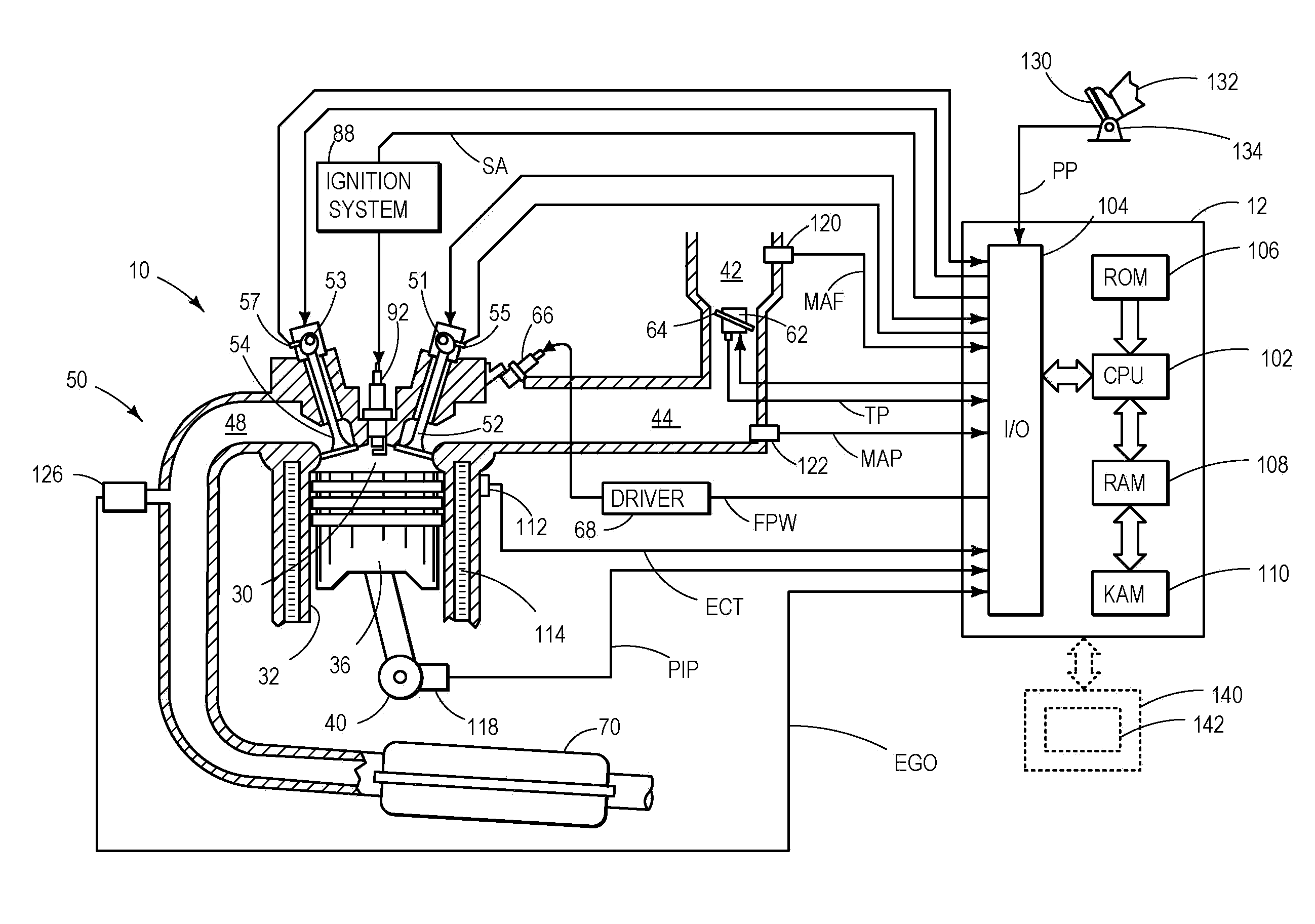
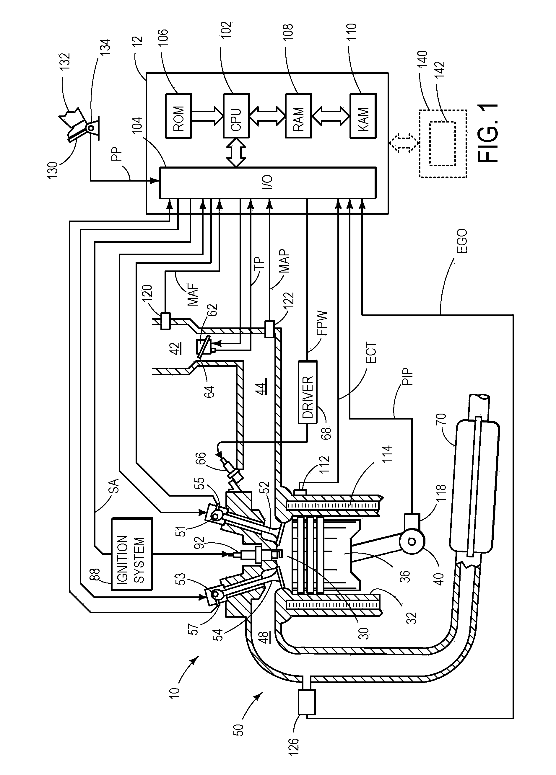
[0015]FIG. 1 is a schematic diagram showing one cylinder of multi-cylinder engine 10, which may be included in a propulsion system of a vehicle in which an exhaust gas sensor 126 may be utilized to determine an air fuel ratio of exhaust gas produce by engine 10. The air fuel ratio (along with other operating parameters) may be used for feedback control of engine 10 in various modes of operation. Engine 10 may be controlled at least partially by a control system including controller 12 and by input from a vehicle operator 132 via an input device 130. In this example, input device 130 includes an accelerator pedal and a pedal position sensor 134 f...


PUM


Abstract

A method for determining degradation of an exhaust gas sensor positioned in an exhaust system for an internal combustion engine of a vehicle is provided. The method includes modulating an air / fuel ratio of gas exhausted by the internal combustion engine to the exhaust system through a cycle that includes at least one rich-to-lean transition and at least one lean-to-rich transition, indicating a degradation condition of the exhaust gas sensor in response to at least one of a rich-to-lean response duration of the exhaust gas sensor and a lean-to-rich response duration of the exhaust gas sensor being greater than a delay threshold, and indicating the degradation condition of the exhaust gas sensor in response to a ratio of the rich-to-lean response duration to the lean-to-rich response duration being greater than an asymmetry threshold that is relative to an axis of symmetry of the rich-to-lean response duration versus the lean-to-rich response duration.

Description

BACKGROUND AND SUMMARY[0001]Typically, an exhaust gas sensor may be positioned in an exhaust system of a vehicle to detect an air / fuel ratio of exhaust gas exhausted from an internal combustion engine of the vehicle. The exhaust gas sensor readings may be used to control operation of the internal combustion engine to propel the vehicle.[0002]Degradation of an exhaust gas sensor may cause engine control degradation that may result in increased emissions and / or reduced vehicle drivability. Accordingly, accurate determination of exhaust gas sensor degradation may reduce the likelihood of engine control based on readings from a degraded exhaust gas senor. In particular, an exhaust gas sensor may exhibit six discreet types of degradation behavior. The degradation behavior types may be categorized as asymmetric type degradation (e.g., rich-to-lean asymmetric delay, lean-to-rich asymmetric delay, rich-to-lean asymmetric slow response, lean-to-rich asymmetric slow response) that affects onl...

Claims


Application Information

Patent Timeline
Patent Type & Authority Applications(United States)
IPC IPC(8): G01M15/10F01N3/00F02D41/00
CPCF01N11/007F01N2550/00F01N2560/025Y02T10/47F02D41/1458F02D41/1475F02D41/1495F02D41/1454Y02T10/40
Inventor KERNS, JAMES MICHAELCLARK, TIMOTHY JOSEPH
Owner FORD GLOBAL TECH LLC
Learn More