Solar collector electronic freeze protection system, with differential circulation control of pump and automatic freeze protection
a solar collector and electronic technology, applied in the direction of solar heat collector controllers, digital computer details, temperatue control, etc., can solve the problems of severe damage to the entire system, the primary cost the construction of the collector itself, so as to eliminate maintenance and replacement costs, simple and cost-effective, and effective solar energy collection
- Summary
- Abstract
- Description
- Claims
- Application Information
AI Technical Summary
Benefits of technology
Problems solved by technology
Method used
Image

Examples
Embodiment Construction
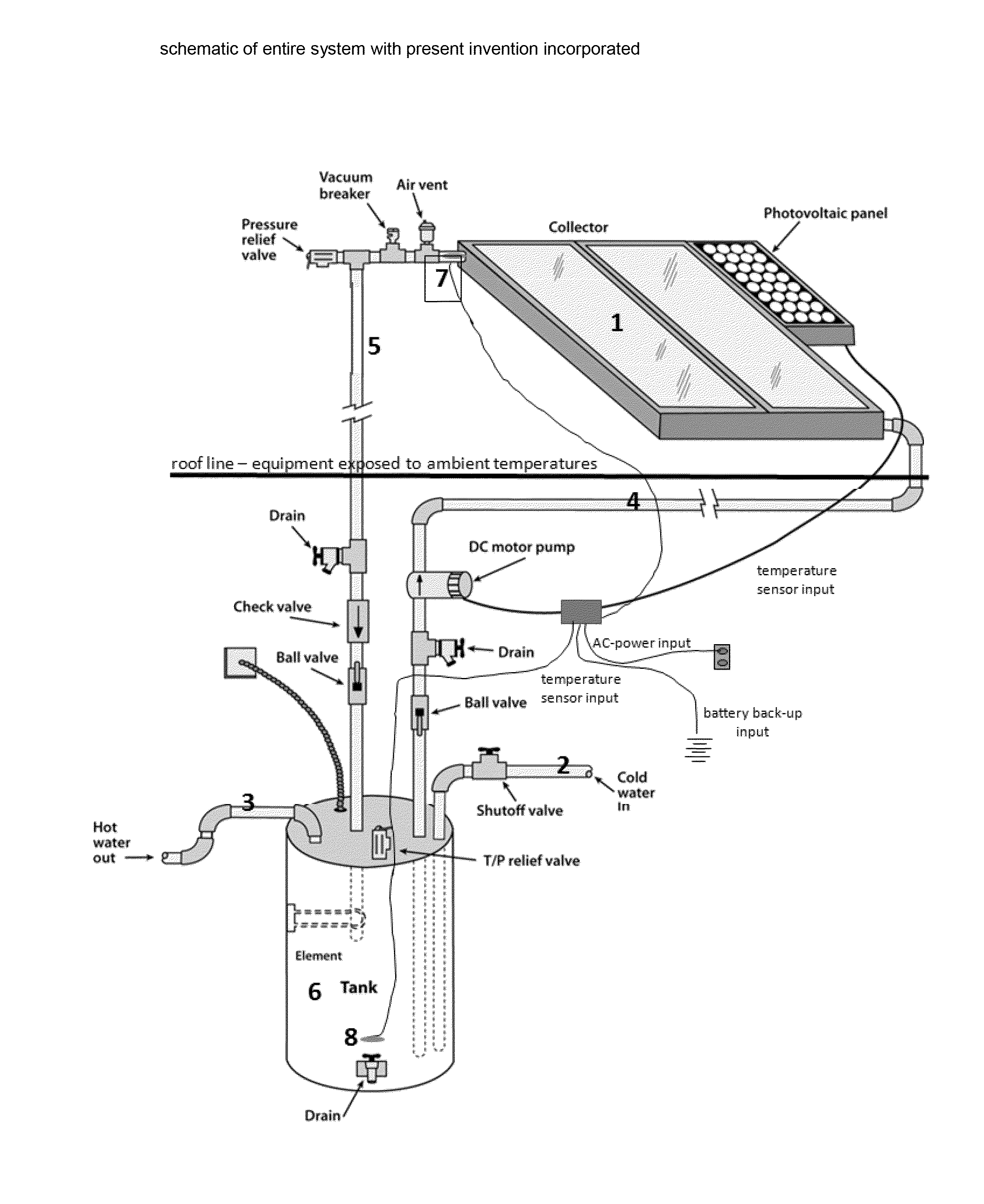
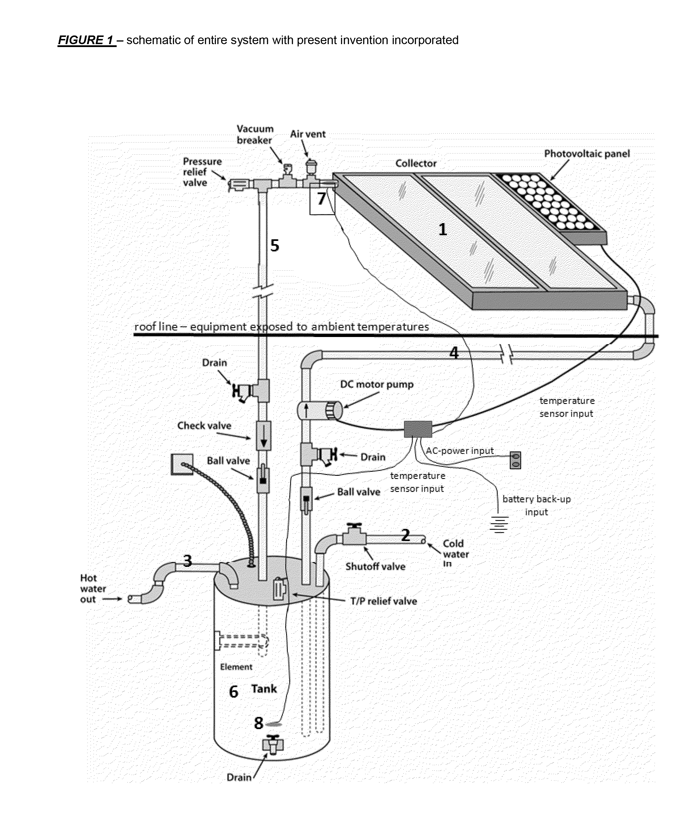
[0011]In accordance with the present invention, a solar energy collection system that avoids all of the inadequacies inherent in the prior art is provided. Specifically, in accordance with the present invention, a system is provided that employs a simple and cost-effective open loop system and, hence, dispenses of the need for AC-powered pump, failure-prone valves, inefficient DC pump control, periodic maintenance, and expensive heat exchangers. Instead, with the present invention, only a single water circulating system is required with water circulating from the collector directly into a water tank for storage or utilization. Sensor fault protection has also been incorporated preventing sensor failures from disabling the freeze protection.
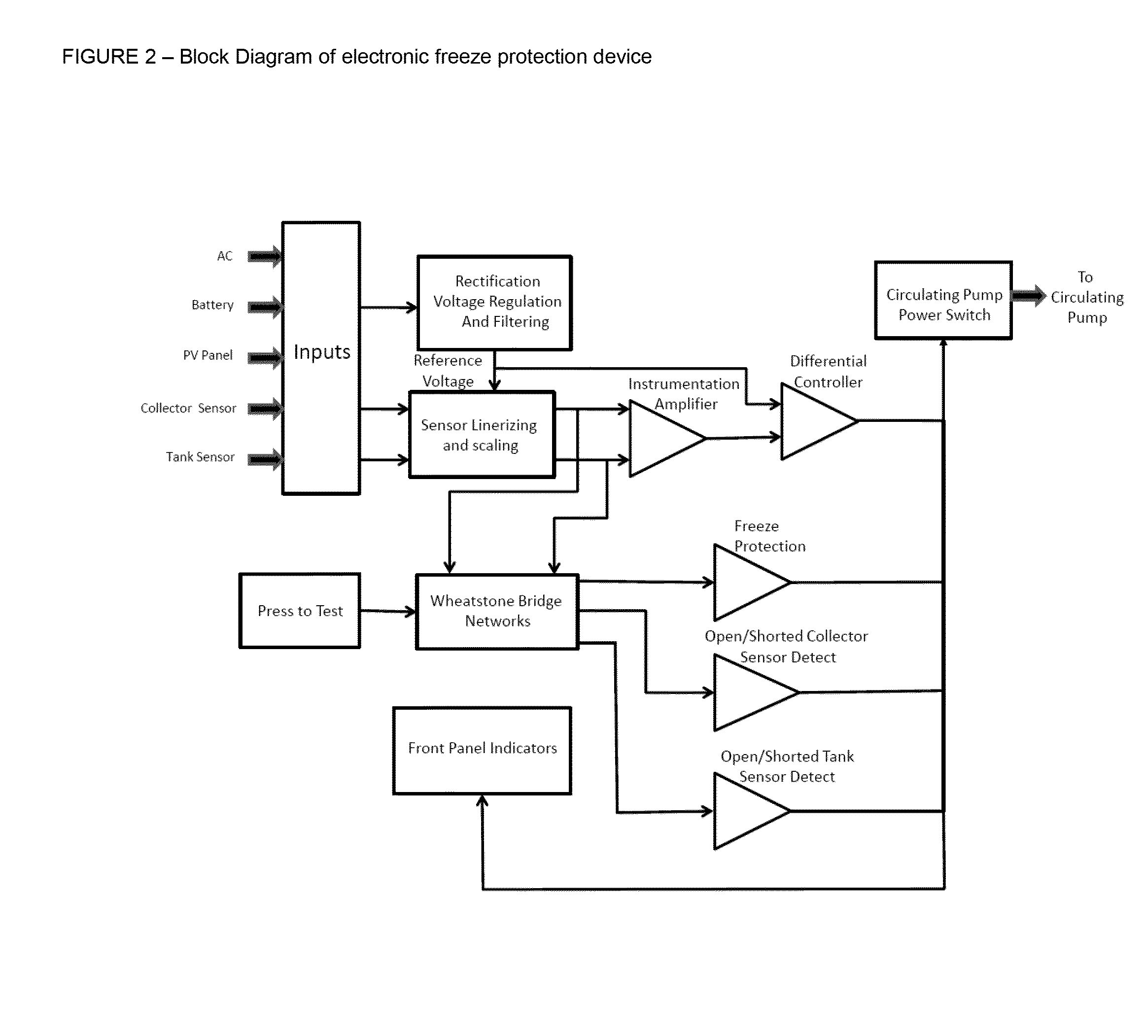
[0012]In order to prevent the water from freezing up in the collector when the temperature drops near or below the freezing point, an automatic and electronic freeze protection system is provided. Specifically, a temperature sensor is affixed at t...
PUM
 Abstract
Description
Claims
Application Information
 - R&D
- Intellectual Property
- Life Sciences
- Materials
- Tech Scout
- Unparalleled Data Quality
- Higher Quality Content
- 60% Fewer Hallucinations
Browse by: Latest US Patents, China's latest patents, Technical Efficacy Thesaurus, Application Domain, Technology Topic, Popular Technical Reports.
© 2025 PatSnap. All rights reserved.Legal|Privacy policy|Modern Slavery Act Transparency Statement|Sitemap|About US| Contact US: help@patsnap.com