Gas Turbine Combustion System
- Summary
- Abstract
- Description
- Claims
- Application Information
AI Technical Summary
Benefits of technology
Problems solved by technology
Method used
Image
Examples
first embodiment
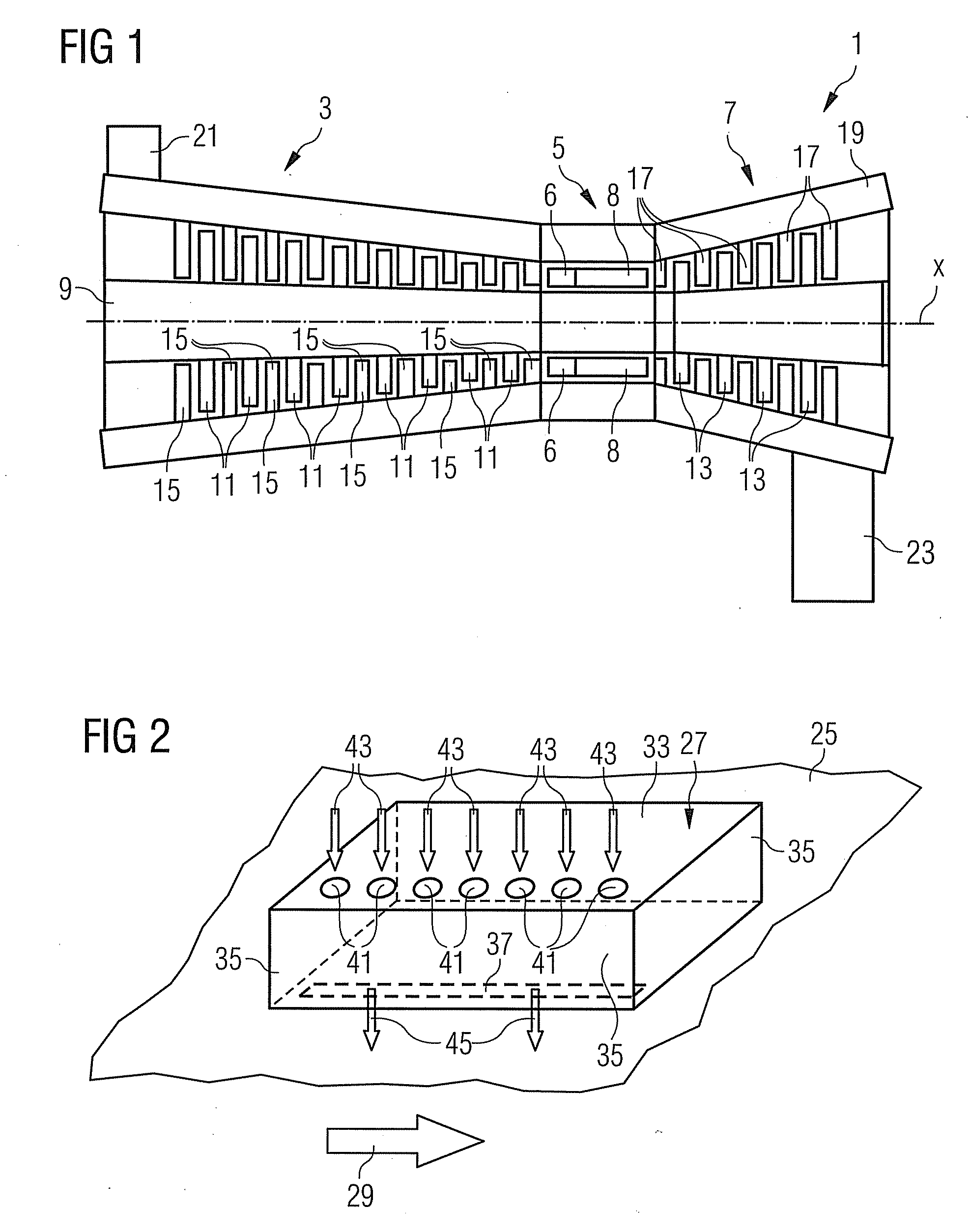
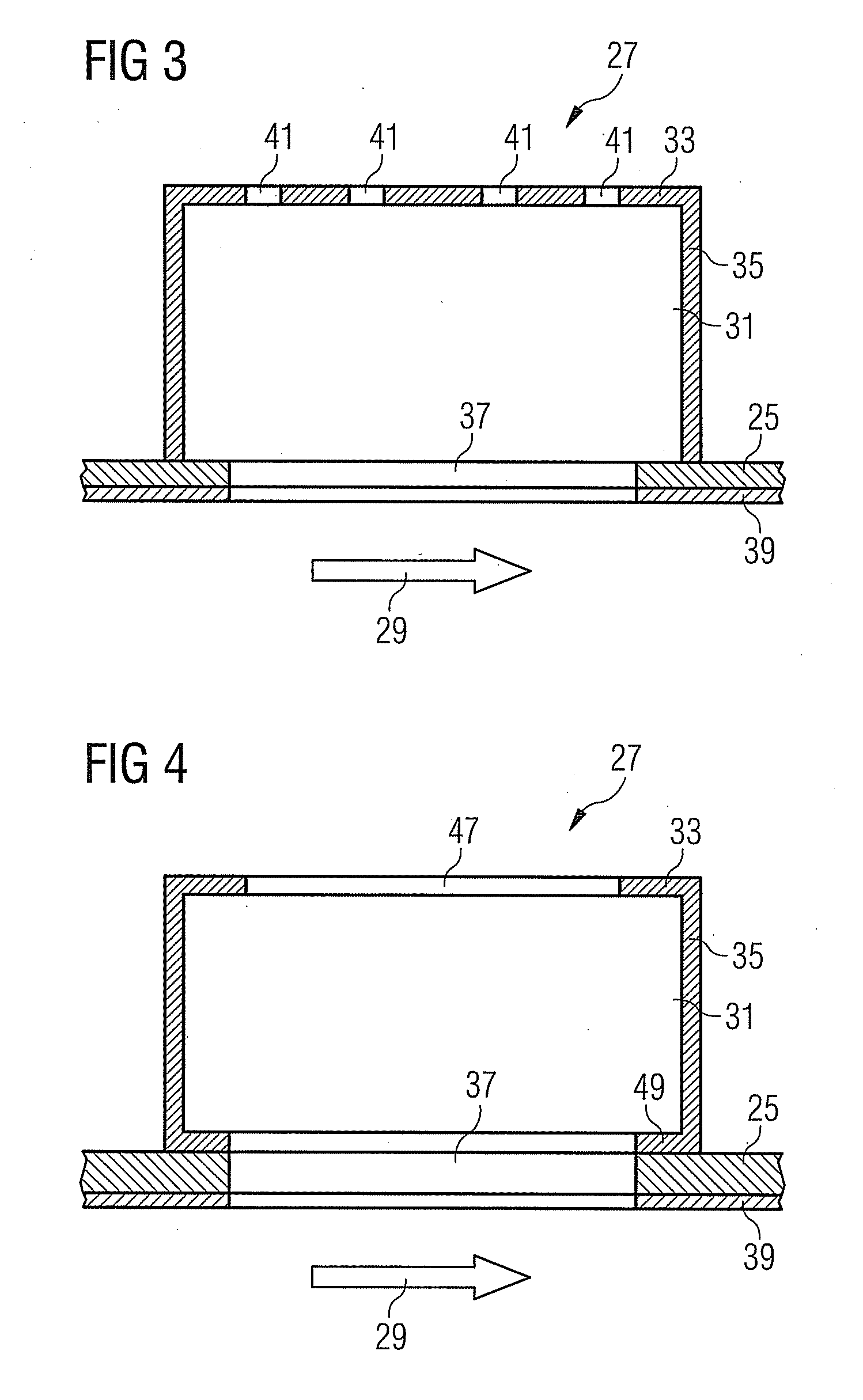
[0026]the gas turbine combustion system according to the invention is depicted in FIGS. 2 and 3. While FIG. 2 schematically shows a three-dimensional view onto a section of a combustor wall or liner 25 which is equipped with a resonator, FIG. 3 shows a sectional view through the resonator 27 and the combustor wall or liner 25. Note that although it will be referred to “combustor wall”25 from now on throughout the embodiments the term “combustor wall” shall also include the meaning of “combustor liner”.
[0027]In the present embodiment, the combustion system wall represented by the combustor wall 25 limits a flow path for hot and pressurized combustion gas. The flow of the hot and pressurized combustion gas is indicated by arrow 29. The resonator 27 is located adjacent to the combustor wall 25 so that the combustor wall 25 and an opposing resonator wall 33, together with circumferential resonator walls 35 extending between the combustor wall 25 and the opposing resonator wall 33, enclo...
second embodiment
[0033]A modification of the second embodiment is shown in FIG. 6. The modification lies in that the line of feed openings 141 is replaced by a feed slot 147 which is aligned with the neck slot 137.
[0034]A third embodiment of the inventive gas turbine combustion system is shown in FIG. 7 which schematically shows a perspective view onto a section of a combustor wall 25 and a resonator 27. Features of the third embodiment which do not differ from features of the first and second embodiments are denominated with the same reference numerals as in the first and second embodiments and will not be explained again.
[0035]The third embodiment differs from the modification of the second embodiment shown in FIG. 6 in that a feed slot 247 is present which although sharing the same orientation with the neck slot 137 is not aligned with the neck slot 137. Instead, the feed slot 247 is located close to a second peripheral wall 35 which lies in opposing relationship to the peripheral wall 35 to whic...
PUM
 Abstract
Description
Claims
Application Information
 - R&D
- Intellectual Property
- Life Sciences
- Materials
- Tech Scout
- Unparalleled Data Quality
- Higher Quality Content
- 60% Fewer Hallucinations
Browse by: Latest US Patents, China's latest patents, Technical Efficacy Thesaurus, Application Domain, Technology Topic, Popular Technical Reports.
© 2025 PatSnap. All rights reserved.Legal|Privacy policy|Modern Slavery Act Transparency Statement|Sitemap|About US| Contact US: help@patsnap.com


