
Systems and Methods for Pre-Warming a Heat Recovery Steam Generator and Associated Steam Lines

a technology of heat recovery steam generator and pre-warming method, which is applied in the direction of machines/engines, liquid degasification, separation processes, etc., can solve the problems of reducing the operational life of the steam turbine or bottoming cycle, elapsed time,

Active Publication Date: 2010-09-23
GENERAL ELECTRIC CO
View PDF8 Cites 18 Cited by
  • Summary
  • Abstract
  • Description
  • Claims
  • Application Information

AI Technical Summary

Benefits of technology

The invention provides systems and methods for pre-warming a heat recovery steam generator (HRSG) and associated steam lines. The technical effects of the invention include improving the efficiency of the HRSG and reducing the time required for the system to reach its maximum operating temperature. The method involves directing heating steam from a steam source to a superheater, a reheater, multiple stages of a steam turbine, and a high pressure evaporator and drum to warm them up. The heating steam is then directed to a bypass line and maintained at a predefined temperature or pressure until it is ready to be directed to the reheater. The system includes a controller for maintaining the heating steam in the bypass line at a predefined temperature or pressure. The method and system can help to improve the speed and efficiency of the HRSG and steam turbine system during startup and transition to maximum operating temperature.

Problems solved by technology

Although the hot exhaust gas from the gas turbine typically flows through the HRSG during the gas turbine start-up, a considerable period of time can elapse before an initially cold HRSG is capable of generating steam at sufficient pressure and temperature.
When the topping cycle was not maintained at a low load for this warm-up phase, the steam turbine or bottoming cycle was subjected to stresses that reduced its operational life.
Parts fatigue, casing and shaft distortions, and physical deterioration of the HRSG system's seals and blades are just some examples of the damage these stresses can cause.
Doing so, however, can reduce the combined cycle system's overall power output, leads to inefficiency, and increases emissions.

Method used


Image

  • Systems and Methods for Pre-Warming a Heat Recovery Steam Generator and Associated Steam Lines
  • Systems and Methods for Pre-Warming a Heat Recovery Steam Generator and Associated Steam Lines
  • Systems and Methods for Pre-Warming a Heat Recovery Steam Generator and Associated Steam Lines

Examples


Embodiment Construction

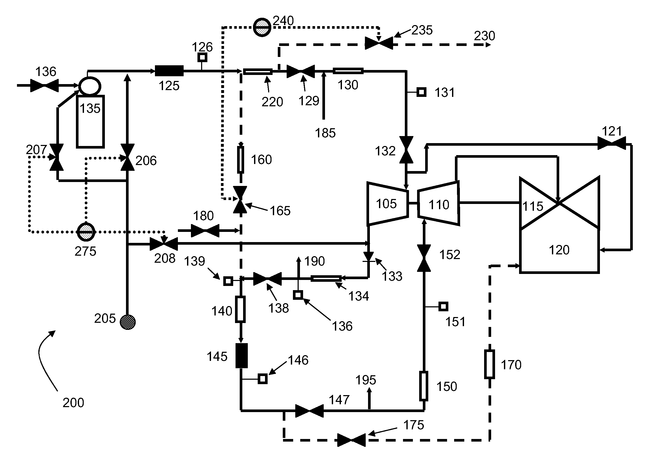
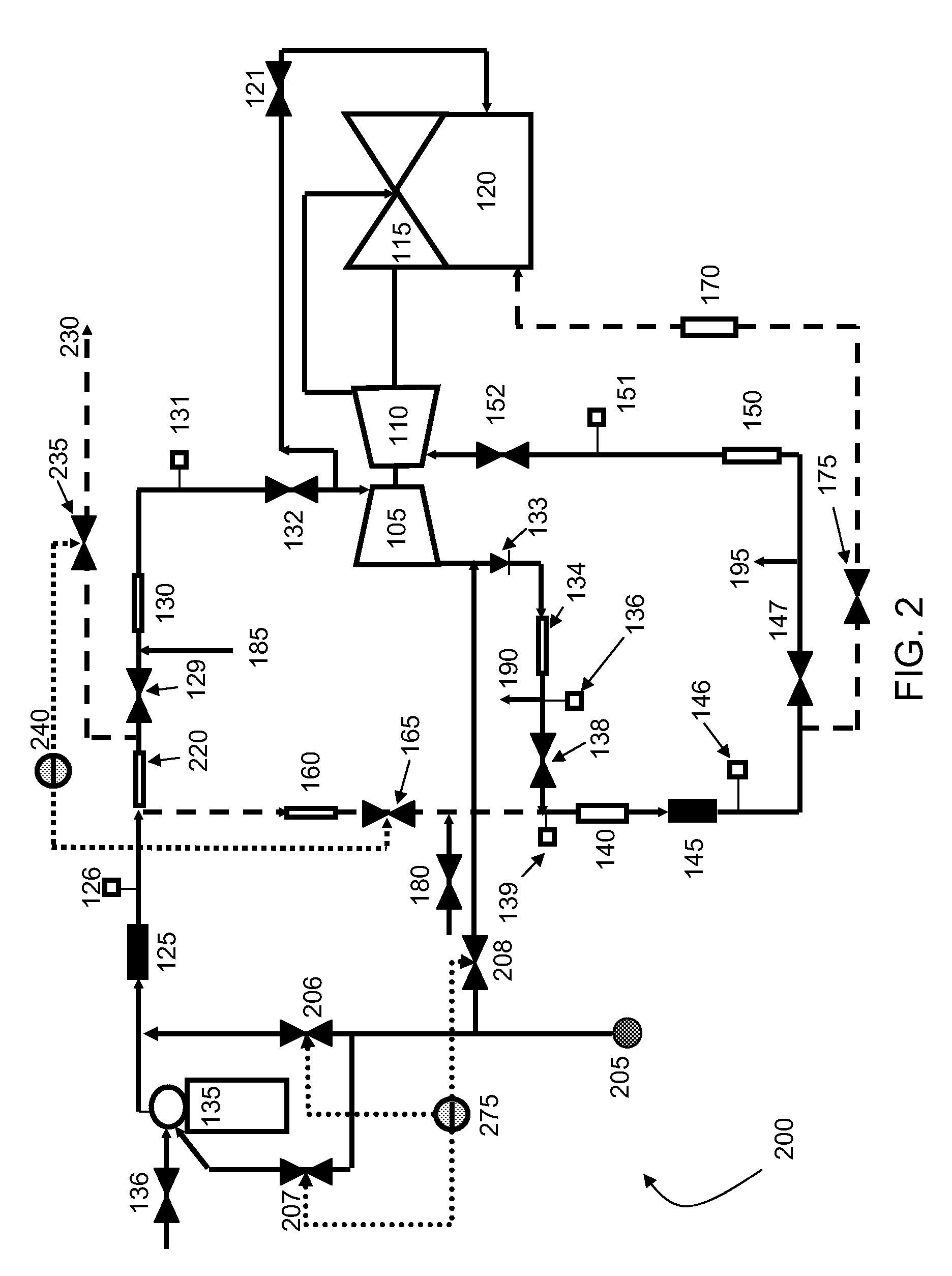
[0015]The invention now will be described more fully hereinafter with reference to the accompanying drawings, in which example embodiments of the invention are shown. This invention may, however, be embodied in many different forms and should not be construed as limited to the example embodiments set forth herein; rather, these embodiments are provided so that this disclosure will convey the scope of the invention to those skilled in the art. Like numbers refer to like elements throughout.

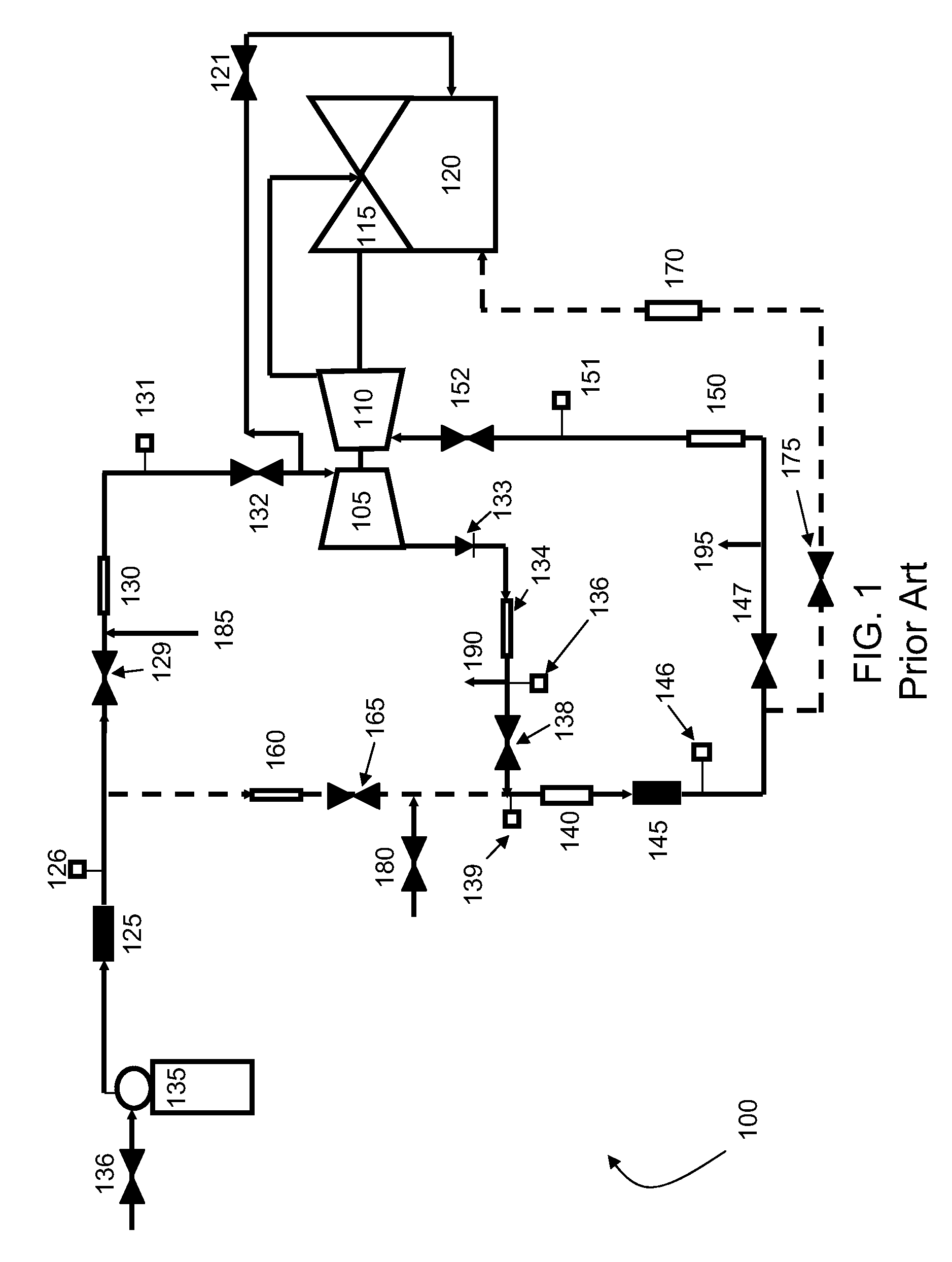
[0016]FIG. 1 illustrates a conventional heat recovery steam generator (“HRSG”) system 100 known in the prior art. In the system 100 shown, steam is cycled through a series of steam turbine stages, including a high pressure stage 105, an intermediate pressure stage 110, and a low pressure stage 115. A condenser 120 is connected to low pressure stage 115 and high pressure stage 105 to collect condensation. Valve 121 connects between the condenser 120 and high pressure stage 105 to control pressure be...


PUM

PropertyMeasurementUnit
timeaaaaaaaaaa
temperatureaaaaaaaaaa
pressureaaaaaaaaaa

Abstract

Embodiments of the invention can provide systems and methods for pre-warming a heat recovery steam generator and associated steam lines. According to one embodiment, a method for pre-warming a heat recovery steam generator can be provided. The method can include providing heating steam from a steam source. The heating steam is directed from the steam source to a superheater so that at least a portion of the superheater can be warmed. Once exiting the superheater, the heating steam can be further directed from the superheater to at least one bypass line and maintained in the bypass line until the bypass line attains a predefined temperature or pressure. Furthermore, the method can include directing, after the bypass line attains a predefined temperature or pressure, at least a portion of the heating steam from the bypass line to a reheater so that the reheater can be warmed.

Description

FIELD OF THE INVENTION[0001]The invention relates to a combined cycle power plant, and more specifically to systems and methods for providing systems and methods for pre-warming a heat recovery steam generator and associated steam lines.BACKGROUND OF THE INVENTION[0002]A combined cycle power plant can use a combination of a gas turbine and a steam turbine to produce electrical power. In a combined cycle power plant, a gas turbine cycle can be operatively combined with a steam turbine cycle by way of a heat recovery steam generator (“HRSG”).[0003]In a combined cycle power plant, the gas turbine cycle can be referred to as a topping cycle, and the steam turbine cycle can be referred to as a steam bottoming cycle. Since the steam turbine or bottoming cycle is driven by heat from the exhaust of the gas turbine or topping cycle, the HRSG does not, in some instances, become fully operational until the gas turbine or topping cycle has increased the steam turbine or bottoming cycle to a sui...

Claims


Application Information

Patent Timeline
Patent Type & Authority Applications(United States)
IPC IPC(8): F01K7/34
CPCF01K13/02Y02E20/16F02C6/18F01K23/10F01K23/101
Inventor HU, TAILAIESTRADA, KELVIN R.ALEXANDER, MICHAEL JOSEPH
Owner GENERAL ELECTRIC CO
Learn More