
Compound imbibing core for thermal column array steam main line and manufacturing method thereof

A technology of liquid-absorbing cores and main channels, which is applied in the field of liquid-absorbing cores, can solve the problems of poor repeatability of manufacturing process, increased liquid return resistance, and small capillary pressure, and achieve the advantages of strong angle adaptability, increased capillary pressure, and enhanced reflux speed Effect

Active Publication Date: 2013-10-02
SOUTH CHINA UNIV OF TECH
View PDF4 Cites 7 Cited by
  • Summary
  • Abstract
  • Description
  • Claims
  • Application Information

AI Technical Summary

Problems solved by technology

The sintered liquid-absorbing core has a large capillary suction force and a large heat transfer, but there is a contradiction that the capillary pressure increases while the resistance of the liquid back increases, and there is a certain directionality; the grooved liquid-absorbing core channel liquid The flow resistance is small, but the capillary pressure is small, the heat transfer is small, and the heat column is very directional; while the wire mesh liquid-absorbing core can obtain high heat transfer performance, but it has been basically eliminated due to poor repeatability of the manufacturing process.

Method used


Image

  • Compound imbibing core for thermal column array steam main line and manufacturing method thereof
  • Compound imbibing core for thermal column array steam main line and manufacturing method thereof
  • Compound imbibing core for thermal column array steam main line and manufacturing method thereof

Examples


Embodiment Construction

[0027] In order to better understand the present invention, the specific implementation method of the present invention will be further described below in conjunction with the accompanying drawings, but the implementation method of the present invention is not limited thereto.

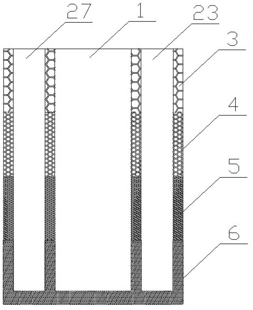
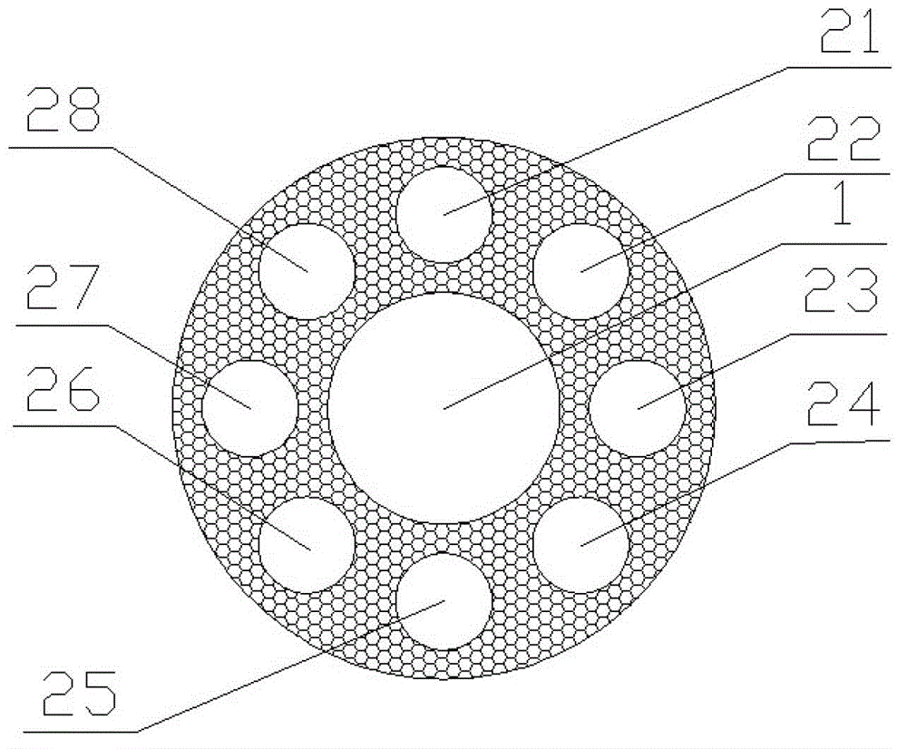
[0028] Such as Figure 1a , Figure 1b As shown, a hot column array steam channel composite liquid absorbent core, the composite liquid absorbent core is a cylindrical structure, including the steam main channel and capillary layer; the capillary layer is a multi-section copper powder sintered capillary layer stacked along the axial direction of the composite liquid absorbent core , different sections of the capillary layer have different porosity, starting from close to the heat source, the capillary layer porosity is arranged from small to large along the axial gradient of the liquid-absorbing core; the particle size of the copper powder used for sintering is 100-400 mesh; the main steam channel It i...


PUM


Abstract

The invention discloses an imbibing core for a thermal column array steam main line and a manufacturing method thereof. The imbibing core comprises a steam main line and capillary layers, wherein the capillary layers are multiple sections of copper powder sintered type capillary layers overlapped along the axle direction of the imbibing core; the capillary layers at the different sections are provided with different porosities; from the position close to a heat source, the capillary layers are arranged in the axle direction of the imbibing core and in a gradient manner according to the porosities in increasing sequences; the steam main line adopts a hollow structure, penetrates the whole capillary layers, and comprises main steam main lines and secondary steam main lines; the main steam main lines are positioned in the center of the cylindrical compound imbibing core; a plurality of secondary steam main lines are positioned at the periphery of the main steam main lines; the secondary main lines are arranged at intervals, and the secondary main steam lines and the main steam lines are arranged at intervals. The compound imbibing core optimizes the structure of the thermal column imbibing core realizes three-dimensional flow of condensation working substances in the axle direction, circumferential direction and radial direction, and has the advantages of low thermal resistance, strong heat-transfer capability, strong suitability for angles, easiness and practicability in manufacturing technique, low cost and the like.

Description

technical field [0001] The invention relates to a liquid-absorbing core, in particular to a thermal column array steam trunk composite liquid-absorbing core and a manufacturing method thereof. Background technique [0002] As a special heat pipe, the heat column has high thermal conductivity, high reliability, fast thermal response, and no need for external driving force. At the same time, the cylindrical evaporation section of the heat pipe is improved into an evaporation plane, so that it can be directly compressed. Suitable for heat conduction on electronic chips, it has become an ideal component for heat dissipation of current high heat flux electronic chips. Due to the rapid development of microelectronics manufacturing technology, the use of highly integrated and miniaturized electronic chips has become the general trend, which has higher requirements for the heat transfer performance of the heat column, so improving the heat transfer performance of the heat column is ...

Claims


Application Information

Patent Timeline
IPC IPC(8): F28D15/04
Inventor 王钒旭丁鑫锐汤勇李宗涛陈光高
Owner SOUTH CHINA UNIV OF TECH
Learn More