
Image compression method and related apparatus

a compression method and image technology, applied in the field of image compression technology, can solve the problems of low compression ratio that can be provided, low raw data and data rate generated by these devices, and low resolution of devices, etc., and achieve the effect of high quality

Inactive Publication Date: 2010-09-16
JMICRON
View PDF18 Cites 15 Cited by
  • Summary
  • Abstract
  • Description
  • Claims
  • Application Information

AI Technical Summary

Benefits of technology

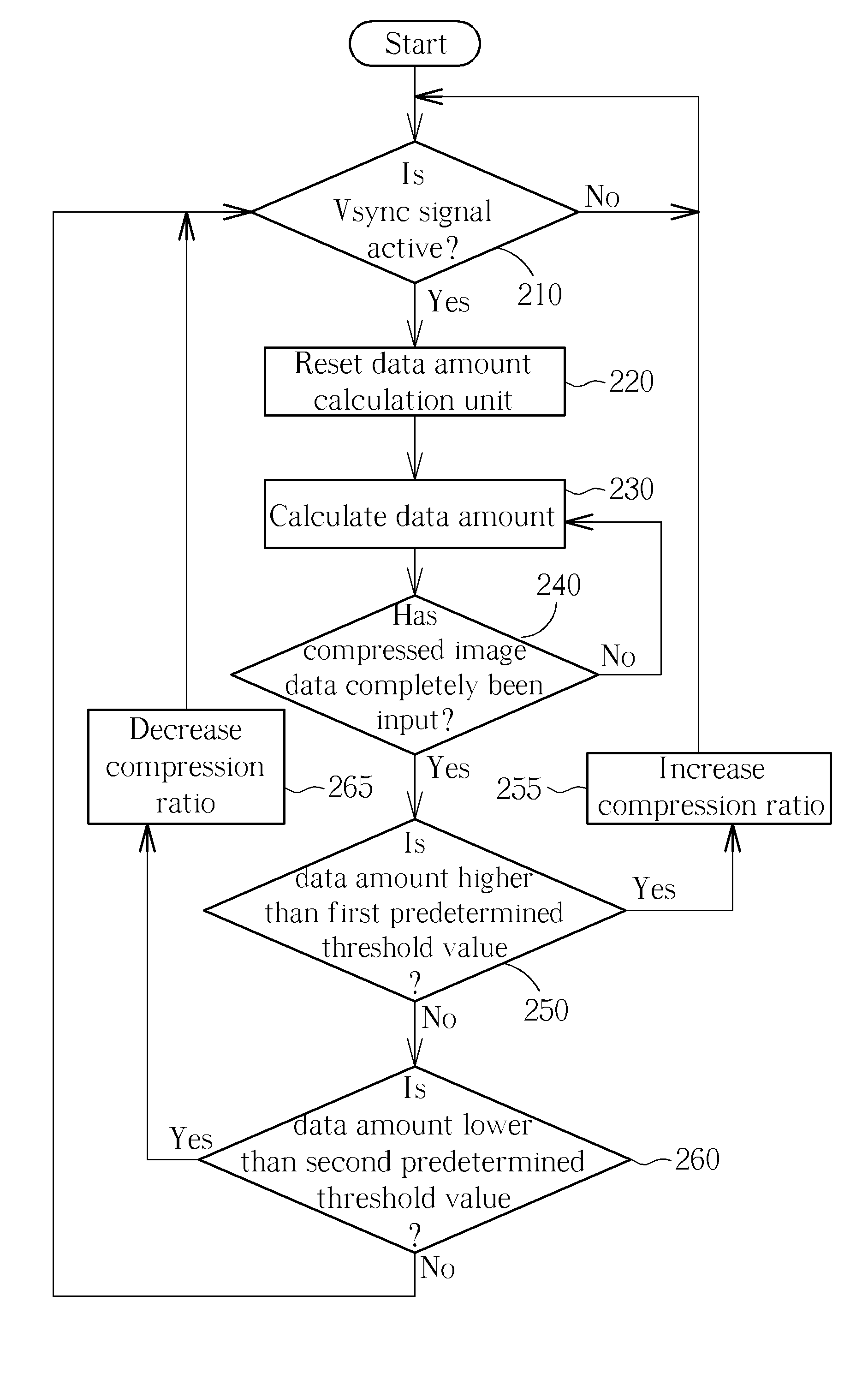
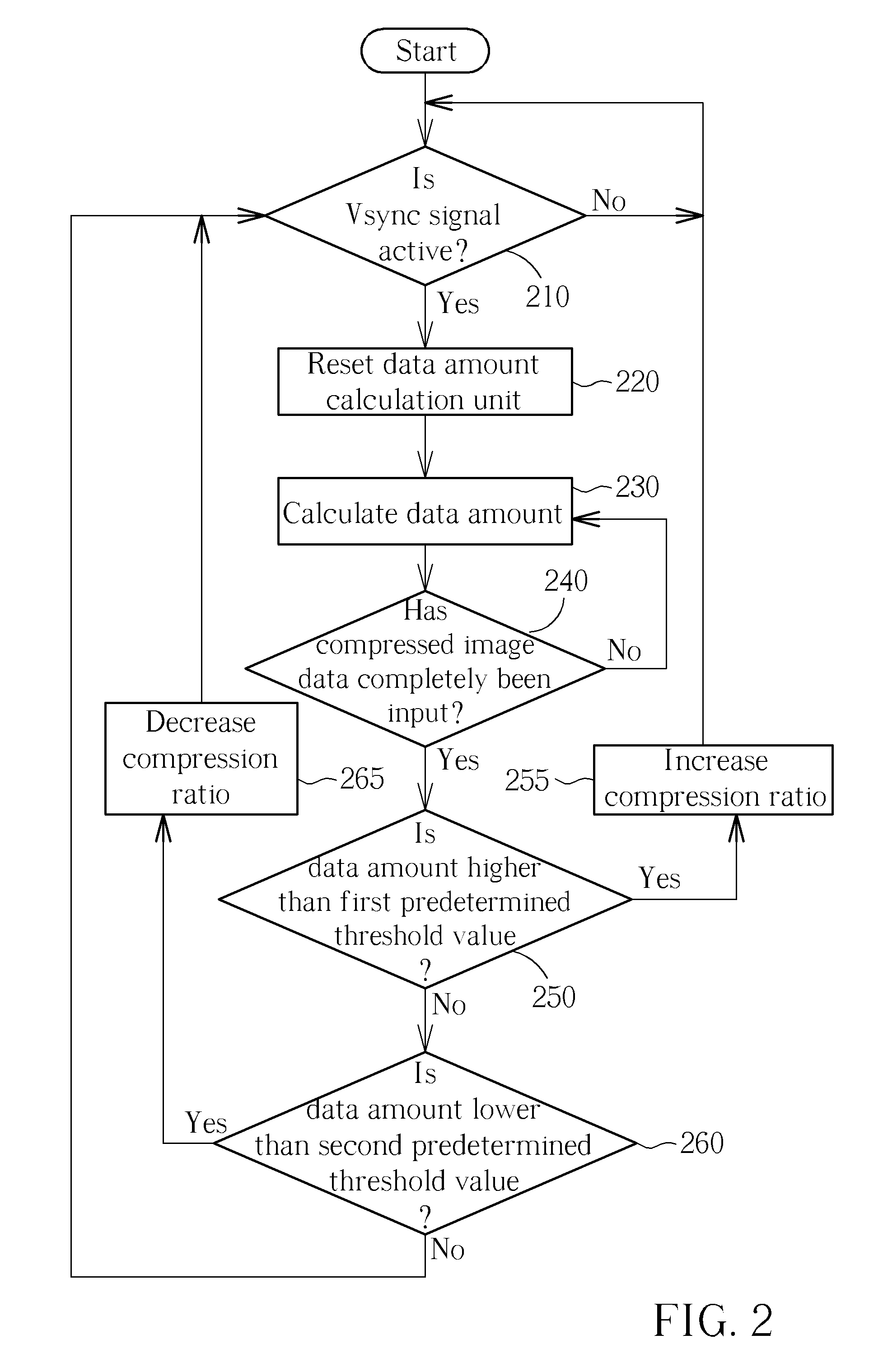
[0009]With this in mind, it is one objective of the present invention to solve the problem faced by the conventional art by dynamically adjusting the compression ratio in accordance with a difference amount between a limited bandwidth and a data amount of compressed image data of each video frame in a video sequence. Thus, the compressed ratio for a next video frame can be properly determined. More precisely, the present invention adjusts the quantization table (corresponding to the compression ratio) according to the variation of the data amount of the compressed image data, thereby deriving a better compressed image quality. As a result, the chosen compressed ratio can be more adaptive and over-compression can also be avoided.
[0013]By the above image compression method and apparatus, the compression ratio for each image data can be dynamically adjusted so as to obtain a compressed image of high quality.

Problems solved by technology

With the development of the Internet and electronic products, this video information can be easily conveyed; however, it is necessary to first process the information utilizing video compression technology due to the limitations of digital data transformation.
Due to its characteristics and design, the compression ratio that can be provided is not very high.
These devices do not have very high resolution, so the raw data and the data rate generated by these devices are not enormous.
However, most data transmission interfaces have limited bandwidths such as Universal Serial Bus (USB) 2.0 interface for 24 MB / s in synchronous transmission.
Therefore, under the limitation of the bandwidth, if the data rate output by the video recording device is too large, an imperfection of the displaying video may occur at the receiving end.
However, the conventional way of determining whether to adjust the compression ratio according to the available space of the buffer cannot properly respond to the following image data in a video sequence, thereby causing over compression of the still images (which do not need a high compression ratio).
As a result, the image quality is sacrificed and the compression efficiency is worse.

Method used


Image

  • Image compression method and related apparatus
  • Image compression method and related apparatus
  • Image compression method and related apparatus

Examples


Embodiment Construction

[0019]MPJEG technology will be taken as an example in the following. It should be noted that those skilled in the art will readily observe that numerous modifications and alterations of the apparatus and method (e.g. other image compression technology) may be made while retaining the teachings of the invention. Thus, these modifications and alterations based on the concept of the present invention should certainly fall within the scope of the present invention.

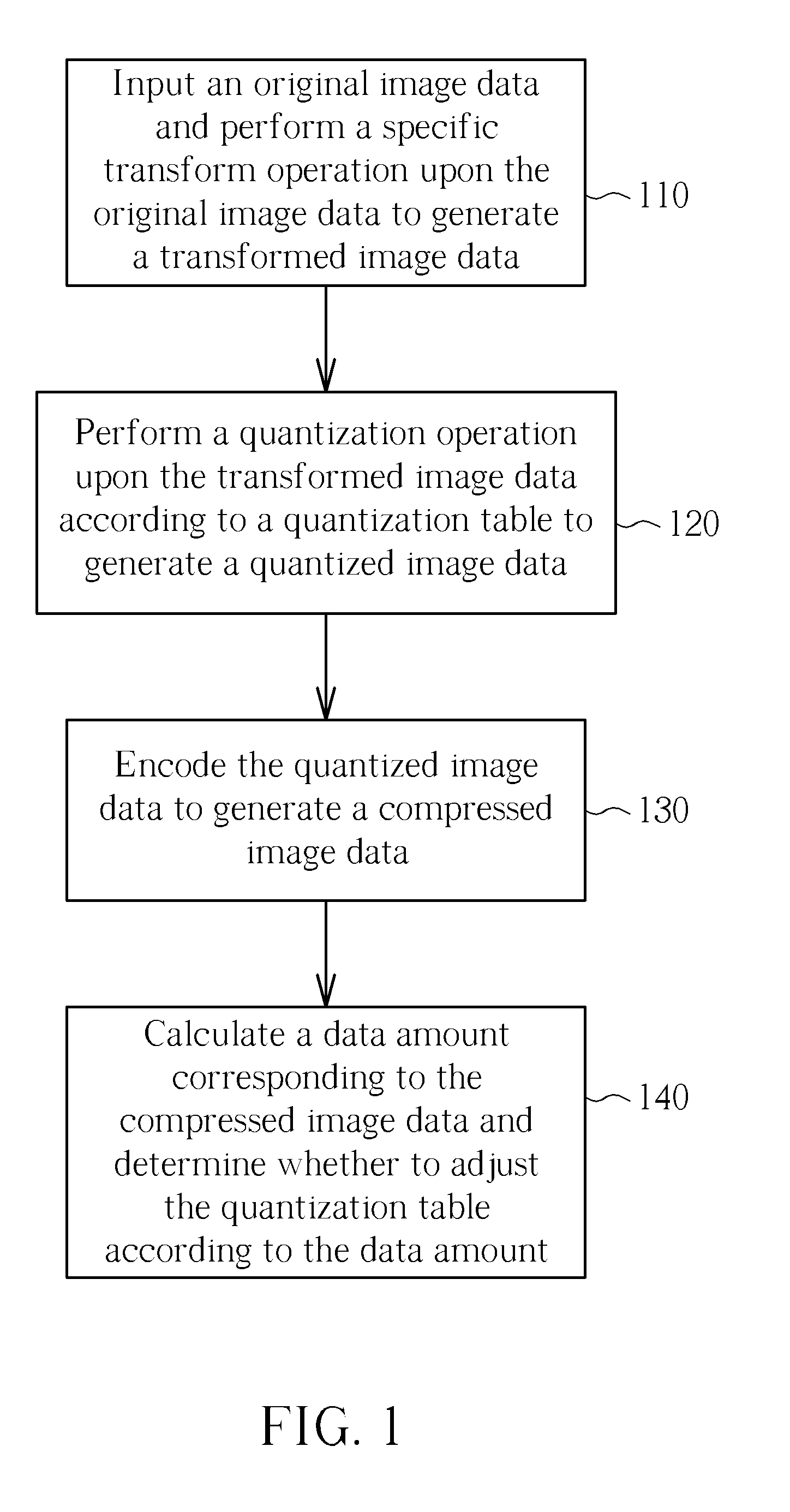
[0020]Please refer to FIG. 1, which depicts a flow chart of the image compression method according to one exemplary embodiment of the present invention. Steps 110-140 expressly illustrate each operation regarding the image compression method of the present invention. In step 110, the image compression method of the present invention performs a specific transform upon a currently input original image data in order to generate a transformed image data. For example, as far as MJPEG is concerned, the original image data includes Y...


PUM


Abstract

An image compression method includes: inputting an original image data and performing a specific transform operation upon the original image data to generate a transformed image data; performing a quantization operation upon the transformed image data according to a quantization table to generate a quantized image data; encoding the quantized image data to generate a compressed image data; and calculating a data amount corresponding to the compressed image data and accordingly determining whether to adjust the quantization table according to the data amount.

Description

BACKGROUND OF THE INVENTION[0001]1. Field of the Invention[0002]The present invention relates to image compression technology, and more particularly, to an image compression method and a related apparatus capable of dynamically adjusting a compression ratio in accordance with an amount of compressed data.[0003]2. Description of the Prior Art[0004]In daily life, people record a variety of video information. With the development of the Internet and electronic products, this video information can be easily conveyed; however, it is necessary to first process the information utilizing video compression technology due to the limitations of digital data transformation. Therefore, various video compression technologies are continually developed by researchers and engineers, of which. MJPEG (Motion Joint Picture Experts Group) technology is one of the earlier compression technologies and H.264 is the most recent. Each standard has different advantages and is suitable for different applicatio...

Claims


Application Information

Patent Timeline
IPC IPC(8): G06K9/36H04B1/66
CPCH04N19/172H04N19/152H04N19/124H04N19/60
Inventor YANG, YI-LECHEN, CHUN-LIANGLO, YU-CHENG
Owner JMICRON
Learn More