
Playback Device For Generating Sound Events

a technology of sound events and playback devices, which is applied in the field of playback devices, can solve the problems of affecting the authenticity of sound events, the clarity of sound events, and the inability to control the audio signals of the different sound sources in each of the mixed audio signals, etc., and achieves the effect of quick configuration of a “custom” signal path

Inactive Publication Date: 2010-09-02
VERAX TECH
View PDF91 Cites 61 Cited by
  • Summary
  • Abstract
  • Description
  • Claims
  • Application Information

AI Technical Summary

Benefits of technology

[0025]According to various embodiments, the path module may configure a signal path for a specific one of the sound objects obtained by the object module. The signal path configured for the sound object may include sound rendering devices that enhance the production of sounds with one or more of the sonic characteristics of the sounds associated with the sound object (e.g., as determined by the object module, described above).
[0037]In some embodiments, the preference module may store a set of templates for signal paths that can be configured by the path module by selectively including or excluding sound rendering devices within a signal path. A given template may be selected by a user (e.g., via the user interface) to initiate configuration of the signal path that corresponds to the given template. These templates may include templates that are pre-programmed to the production processor, downloaded from an external source (e.g., the Internet, a removable storage media, and / or other sources.), obtained with the sound objects associated with a given sound event, or obtained from some other source. In some instances, the templates may be adjusted by a user, or even created completely by the user. The templates may enable a user to quickly configure a “custom” signal path without having to manually select individual sound rendering devices for inclusion or exclusion in the signal path.
[0038]According to various embodiments, the preference module may automatically track user interaction with the path module, and may suggest preferences to the user. For example, the preference module may track the signal paths configured by the user over time, and may identify a signal path configuration that is repeatedly created by the user. The preference module may then present this signal path configuration to the user with the suggestion that the configuration be saved as a template. Upon approval from the user, the preference module may then save the signal path configuration as a template. As another non-limiting example, the preference module may identify a modification that the user repeatedly makes to the configuration of a signal path that corresponds to a given template. The preference module may present an option to the user to modify the given template in accordance with the modification, which may relieve the user from having to make this modification in the future. Similarly, the preference module may present an option to the user to create a new template that corresponds to the given template with the exception of the modification that is frequently made by the user. This may relieve the user of having to make the modification in the future, while still enabling the user to access the given template in its unaltered form.
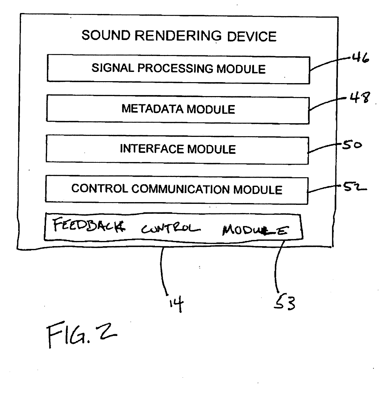
[0051]The control communication module may manage communication between the sound rendering device and one or more other components of the playback device. For example, the control communication module may receive information from and / or transmit information to the production processor. The information communicated by the control communication module may include the communication of device metadata from the sound rendering device to the production processor (e.g., to the rendering device module). This communication may enable the production processor to make determinations with respect to which sound objects will be assigned to signal paths that include the sound rendering device.
[0052]The feedback control module may be configured to capture and / or process feedback information that can be provided to one or more other components of the playback device (e.g., the production processor) to enhance the production of sounds by the sound rendering device. In some embodiments, the feedback information may include sound information actually being produced by the sound rendering device (e.g., recorded by a transducer on the sound rendering device). The sound information may then be provided to the production processor via the feedback control module to enable the production processor to compare sound actually being produced by the sound rendering device with the sound intended for the sound rendering device, and to adjust control of the sound rendering device in a feedback manner. The feedback control module may implement some or all of the feedback functionality locally at the sound reproduction device, thereby reducing processing load on the production processor 26. For example, the feedback control module may process the sound produced by the sound rendering device and may analyze the sound to ensure accuracy with respect to sounds that should be produced, adjust performance of the sound rendering device on a feedback basis, diagnose maintenance and / or other system hardware issues, and / or provide other functionality based on the captured sound information.

Problems solved by technology

However, once mixed, the audio signals associated with the different sound sources in each of the mixed audio signals cannot be separately controlled.
Further, the authenticity of the sound event, the clarity of the sound event, and / or other aspects of the event may be diminished due to known effects produced by mixing audio signals representing sounds with different sonic characteristics.
However, conventional playback devices may be limited with respect to the manner in which the separate audio signals are used to generate the sounds of the sound event.

Method used


Image

  • Playback Device For Generating Sound Events
  • Playback Device For Generating Sound Events
  • Playback Device For Generating Sound Events

Examples


Embodiment Construction

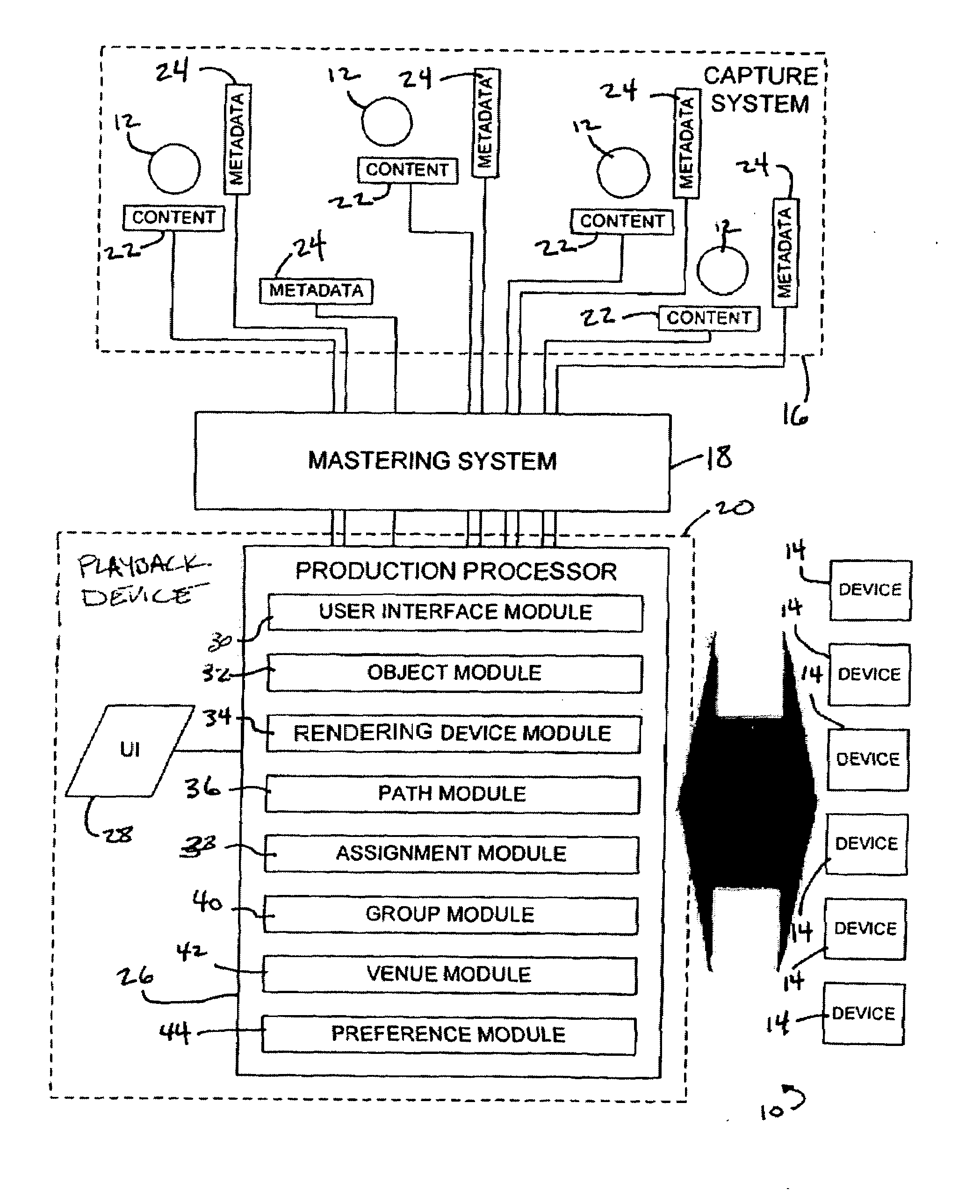
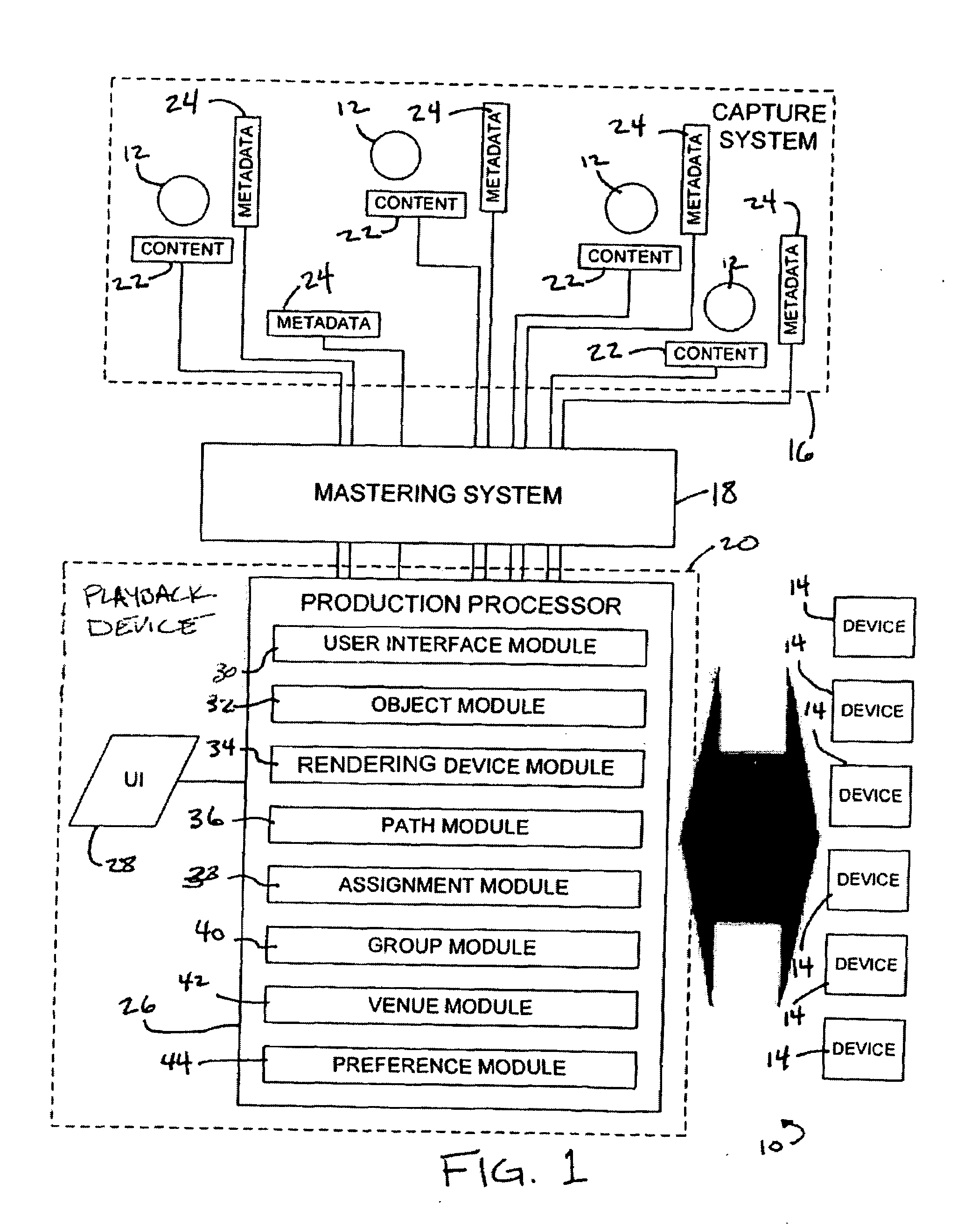
[0058]FIG. 1 illustrates a system 10 configured to capture and / or produce a sound event generated by a plurality of sound sources 12, according to one or more embodiments of the invention. System 10 may capture and process signals corresponding to sounds generated by separate ones of sound sources 12 during a sound event in a discretized and / or separate manner so as to enhance production of the sound event by a plurality of sound rendering devices 14. The production of the sound event by sound rendering devices 14 may be enhanced in reality, customization, clarity, configurability, and / or otherwise enhanced. In some embodiments, system 10 may include a capture system 16, a mastering system 18, a playback device 20, and / or other components.

[0059]As used herein, the term “sound source” may denote any object or set of objects that produce sound. For example, in some instances, a single musical instrument may form a sound source. In some instances, a plurality of instruments may form a ...


PUM


Abstract

A system configured to capture and / or produce a sound event generated by a plurality of sound sources. In particular, the system may be configured such that the capture, processing, and / or output for sound production of sound objects associated with separate ones of the sound sources may be controlled on an individual based. This discretized control over the sound objects may enhance various aspects of productions of the sound event by systems that do not capture, process and / or output sounds from different sound sources in a manner that maintains the discrete nature of the sound sources.

Description

RELATED APPLICATIONS[0001]This application is related to U.S. Pat. No. 7,289,633, issued Oct. 30, 2007, U.S. Pat. No. 7,085,387, issued Aug. 1, 2006, U.S. patent application Ser. No. 11 / 048,783, filed Feb. 3, 2005, U.S. patent application Ser. No. 11 / 407,965, filed Apr. 21, 2006, U.S. Pat. No. 6,239,348, issued May 29, 2001, U.S. Pat. No. 6,444,892, issued Sep. 3, 2002, U.S. Pat. No. 6,740,805, issued May 25, 2004, U.S. Pat. No. 7,138,576, issued Nov. 21, 2006, U.S. patent application Ser. No. 11 / 131,275, filed May 18, 2005, U.S. patent application Ser. No. 11 / 592,141, filed Nov. 3, 2006, and U.S. patent application Ser. No. 11 / 260,171, filed Oct. 28, 2005, U.S. patent application Ser. No. 11 / 358,063, filed Feb. 22, 2006. All of these patents and applications are hereby incorporated by reference into this disclosure in their entirety.FIELD OF THE INVENTION[0002]The invention relates to playback devices that obtain audio signals and drive sound rendering devices (e.g., amplifiers, sp...

Claims


Application Information

Patent Timeline
Patent Type & Authority Applications(United States)
IPC IPC(8): G06F3/00
CPCH04R29/008H04S2400/15H04S2400/11H04S3/008
Inventor METCALF, RANDALL B.
Owner VERAX TECH
Learn More