
Open lumen air filtration for liquid lines

a technology of liquid line and open lumen air, which is applied in the direction of liquid degasification, liquid degasification by filtration, separation process, etc., can solve the problems of bubbles interrupting and/or blocking affecting the flow of fluid, etc., so as to reduce the overall resistance to flow, and reduce the effect of mechanical resistan

Active Publication Date: 2010-09-02
HEKMAT NEEMA +1
View PDF26 Cites 27 Cited by
  • Summary
  • Abstract
  • Description
  • Claims
  • Application Information

AI Technical Summary

Benefits of technology

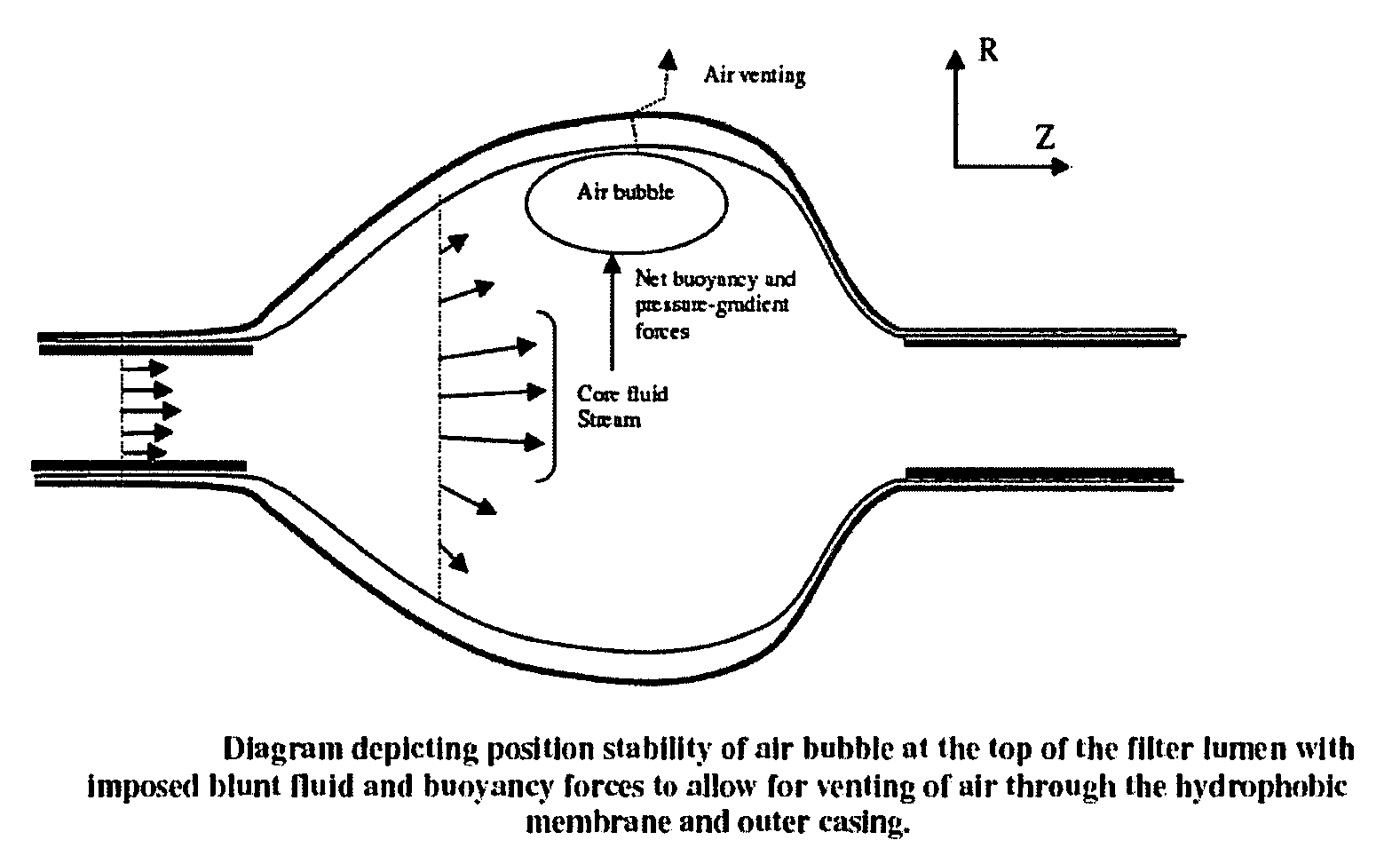
[0035]The axisymmetric design provides air filtering under all orientations, with optimal filtration performance under all flat rotational orientations. The device provides >80% filtration performance under low Reynolds numbers (less than ˜10).
[0036]The design of the present invention means that filtration efficacy is generally not dependent on infusion rate (flow rate) under stable flow conditions. Our tests have shown stability in flow models simulating flows of up to 1200 cc / hr in a 8 Fr. compatible device (or Reynolds numbers of less than 4800). Unstable flow conditions occur when the Reynolds has reached the point where the fluid boundary layers are no longer separated by a core fluid stream and all fluid within the device is in a mixing regime.
[0037]The design of the present invention does not use a split channel design, but uses a single channel design, thereby reducing overall resistance to flow when compared with the split channel design. The single, continuous lumen imposes minimal mechanical resistance on flow and infusion capacity. In a split channel configuration, there is a split in a liquid line, in other words, a bifurcation or division of a central or inlet flow into two / more liquid channels. The split channel design filter has multiple (i.e. more than one) parallel-arranged paths for liquid flow. Therefore, in a split channel design filter liquid can take more than one fluid path from the device's inlet to its outlet. In the case of a medical filter employing this split channel design, the “split channels” are lined with a hydrophobic or other air-filtering membrane. The “split channels” are intended to increase the filtration surface area-to-air volume ratio to enhance filtration efficacy.

Problems solved by technology

This problem is of considerable importance in various applications in which a liquid is conducted through a conduit, and is particularly troublesome in medical applications.
Currently, there is no adequate solution to this problem.
These bubbles can interrupt and / or block the flow of a fluid.
Such blockage or interruption can be problematic for many sorts of medical and industrial equipment where an uninterrupted flow is desirable.
Many analytical and diagnostic devices, especially those that employ the flow of very small volumes of a liquid, are very sensitive to such interruptions in flow.
These problems are particularly acute in microfluidic applications.
In a medical context, when intubation is required, for example with a catheter, drip or other conduit designed to introduce (or remove) liquid from the body of a subject, such blockage or interruption can have adverse consequences and can even be fatal, such as when an air bubble enters the blood stream.
Less risk is associated with the use of peripherally inserted central catheters (PICC), but the risk of embolization is still a serious one.
However the use of use of these air venting filters is limited primarily by their split channel design, which does not allow for compatibility with catheters, sheaths and endovascular interventional devices that largely require simultaneous passage of liquid and catheters / wires.
Other limitations of these current technologies include an inherent dependence on infusion rate (flow rate) to control filtration efficacy, i.e. at higher flow rates, gases pass through the micro-channels faster and carry less contact with hydrophobic vent membranes.
Also, the current technologies suffer from undesirable mechanical resistance to flow due to the split channel design.
The current solutions, for example manual flushing of lines of openable valves positioned within a line, present other inherent problems.
One current deficit is that the process of recognizing the presence or gas bubbles in the line is visual and requires active checking.
Another deficit is that the process of removal of gas bubbles is manual and subject to human error.
A further deficit is that such methods cannot remove air bubbles that may arise subsequent to checking and insertion of the line, such as when gas comes out of solution due to the effects of increasing temperature and or decreasing pressure.
Another deficit of the current solution is that the efficiency of removal of air bubbles is at least partially dependent upon having a reasonably low fluid flow rate through the line.
Many infusing solutions (such as radio-opaque contrast solutions) are infused at a relatively fast rate, and thus, the current air venting mechanisms are not a viable solution.
None of the current solutions contains an air bubble capture system or bubble trap that removes gas bubbles from the flowing liquid irrespective of the rate of liquid flow through the tube.
Additionally, the current solutions do not adequately address the removal of air bubbles arising from the connection or re-connection of fluid lines and insertion of catheters / wires into, for example, a guide / introducer sheath.

Method used


Image

  • Open lumen air filtration for liquid lines
  • Open lumen air filtration for liquid lines
  • Open lumen air filtration for liquid lines

Examples


Embodiment Construction

[0055]The invention provides devices, systems, methods and kits for removing accumulated gas bubbles in a liquid-carrying line.

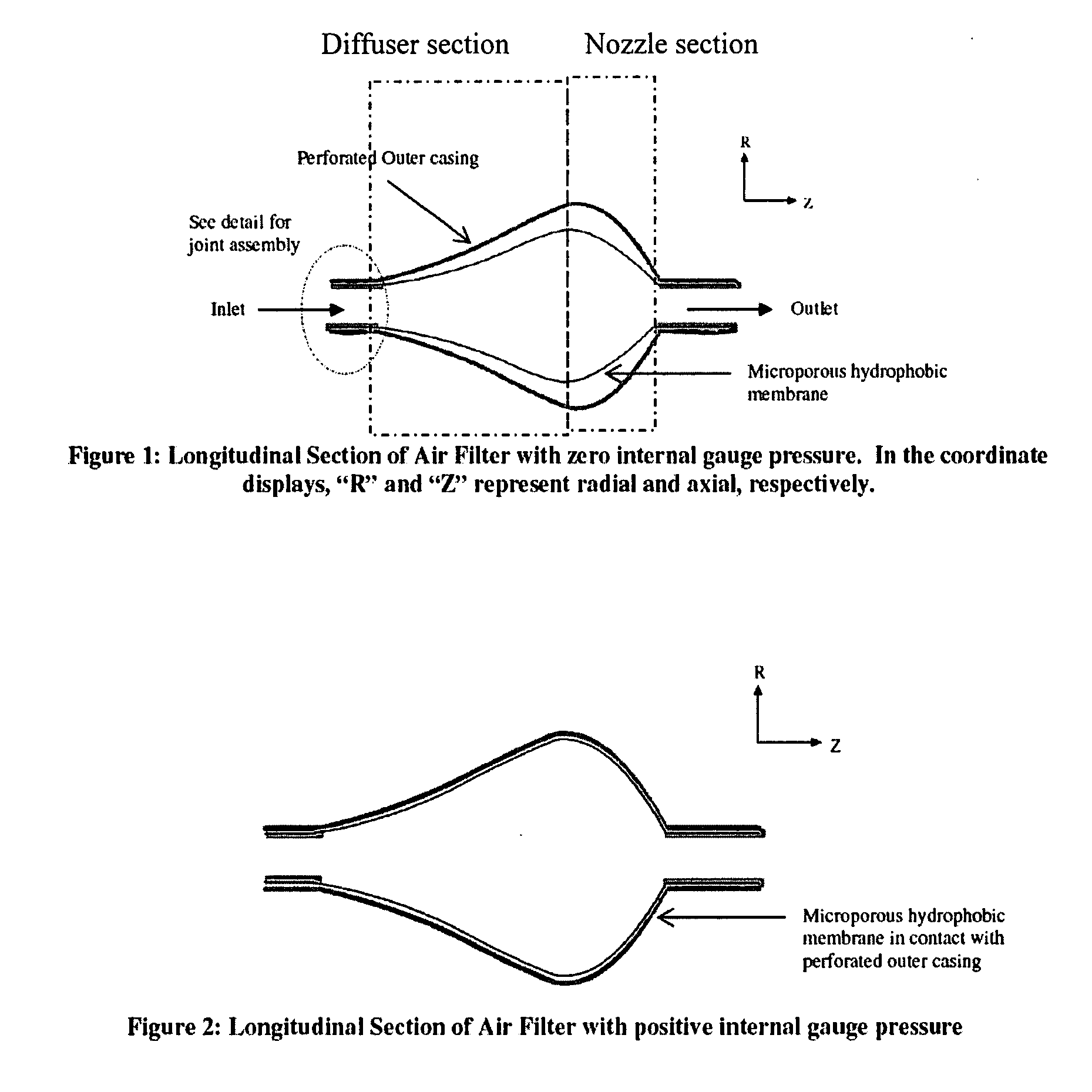
[0056]Embodiments of the present invention encompass a device that filters, captures and vents gas bubbles from a liquid-carrying line. The filter of the invention maintains an open lumen to allow for insertion of tubes and wires (e.g. catheters and guidewires for endovascular intervention related applications) through the device concurrent with liquid infusion through the device.

[0057]Important advantages of the present design include the following: (1) The design of the present invention allows gas capture and venting while concurrently using instruments passing through the conduit, such as catheters, sheaths and endovascular interventional devices. (2) The design of the present invention means that filtration efficacy is not dependent on infusion rate (flow rate). (3) The design of the present invention does not use a split channel design, but uses a sing...


PUM

PropertyMeasurementUnit
diameteraaaaaaaaaa
Reynolds numbersaaaaaaaaaa
average diameteraaaaaaaaaa

Abstract

Devices and systems for capturing and removing accumulated gas bubbles in a liquid-carrying line wherein the device is an expanded double-layered chamber designed and adapted to be integrally placed within the flow pathway of a liquid-carrying line. The device allows insertion of tubes and wires through the device while in use without occlusion of the fluid flow path and without interruption of the bubble-removing function. The efficiency of the air venting and bubble-removing process is not dependent on the fluid flow rate under stable flow conditions, and the device works to remove air bubbles under a range of orientations.

Description

BACKGROUND[0001]The problem of gas bubbles in a fluid-carrying line is very a long-standing and well-known one. This problem is of considerable importance in various applications in which a liquid is conducted through a conduit, and is particularly troublesome in medical applications. Currently, there is no adequate solution to this problem. Gasses may enter the fluid-filled line in a gaseous state as bubbles within the fluid, or it may be present in a dissolved state within the fluid, and come out of solution under the influence of changing pressures or temperatures. The gas molecules so produced coaless under entropic and hydrophobic influences to form discrete bubbles within the fluid. These bubbles can interrupt and / or block the flow of a fluid. Such blockage or interruption can be problematic for many sorts of medical and industrial equipment where an uninterrupted flow is desirable. Many analytical and diagnostic devices, especially those that employ the flow of very small vol...

Claims


Application Information

Patent Timeline
Patent Type & Authority Applications(United States)
IPC IPC(8): B01D19/00
CPCA61M1/3627B01D19/0036B01D19/0031A61M5/385
Inventor HEKMAT, NEEMAYAP, LIPKONG
Owner HEKMAT NEEMA
Learn More