
System and Method for Managing the Power-Performance Range of an Application

a technology of power-performance range and application range, which is applied in the direction of instruments, generating/distributing signals, computation using denominational number representation, etc., can solve problems such as speeding up processor performance adjustment, and achieve the effect of improving processor power-efficiency and sacrificing any performan

Inactive Publication Date: 2010-08-26
IBM CORP
View PDF28 Cites 57 Cited by
  • Summary
  • Abstract
  • Description
  • Claims
  • Application Information

AI Technical Summary

Benefits of technology

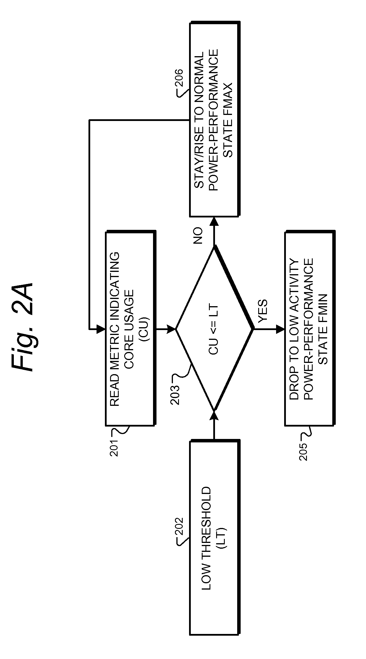
[0004]This invention provides a means to support power-performance trade-offs for any given time interval, within a range set by the higher level controller. Semiconductor device circuits and methods are provided for adjusting core processor performance based on usage metrics. Metric detection and adjustment are performed in digital logic hardware guided by registers providing maximum and minimum frequency settings, without intervening input from system software or firmware, thus greatly speeding the processor performance adjustment. Power-performance drivers provide applications or the operating system ability to specify maximum and minimum frequency requirements.
[0009]The use of hardware digital logic without software intervention, rather than software or firmware-based solutions, can provide many advantages. The software solutions have only limited opportunities to examine metrics and initiate power-performance changes. Firmware performing the same task is also typically slow to respond. Real workloads can show much more fine-grained variation in frequency demands than the system software / firmware can react to. The preferred embodiments herein provide an automated hardware method for recognizing and acting upon opportunities for rapid state changes / scaling to match the fine-grained demands of workloads. This can improve the power-efficiency of the processor without sacrificing any performance, by matching the hardware operating state to the exact demands of the workload.

Problems solved by technology

Metric detection and adjustment are performed in digital logic hardware guided by registers providing maximum and minimum frequency settings, without intervening input from system software or firmware, thus greatly speeding the processor performance adjustment.

Method used


Image

  • System and Method for Managing the Power-Performance Range of an Application
  • System and Method for Managing the Power-Performance Range of an Application
  • System and Method for Managing the Power-Performance Range of an Application

Examples


Embodiment Construction

[0016]FIG. 1 is a high-level system block diagram of a computer system of one preferred embodiment. The depicted system 100 includes software portion 101 having an operating system or a hypervisor manager, for example, and includes power management software drivers and firmware. A preferred version also includes an API (application programming interface) exposing power management functions to applications that run on the operating system or on the hypervisor virtual machines. Power control API drivers provide access to configure automatic power control circuits within the depicted processor core chiplet 102.

[0017]The depicted chiplet 102 is, in a preferred embodiment, one of many processor core chiplets present on a single semiconductor device. As used herein, a chiplet is a complete subsystem IP core, or a semiconductor circuit instantiation of such a core, that may connect to interfaces both internal to a system-on-chip (SOC) and at its pads. Each chiplet typically contains severa...


PUM


Abstract

Semiconductor device circuits and methods are provided for adjusting core processor performance based on usage metrics. Metric detection and adjustment are performed in digital logic hardware guided by registers providing maximum and minimum frequency settings, without intervening input from system software or firmware, thus greatly speeding the processor performance adjustment. Power-performance drivers provide applications or the operating system ability to specify maximum and minimum frequency requirements.

Description

TECHNICAL FIELD OF THE INVENTION[0001]This invention relates to improving energy efficiency in microprocessors, and more specifically to systems on board the microprocessor integrated circuit for managing the power-performance range of an application by providing ability to specify a minimum and maximum frequency range.BACKGROUND OF THE INVENTION[0002]Processors in computers employ variable power-performance states to match operating states to processor load. Modern processors incorporate dynamic voltage and frequency scaling as integral mechanisms to tailor operating states. These operating state changes are typically managed by the operating system or system firmware using explicit, special instructions to cause processor operating state change. Management of these states by the system software layer is typically designed to take a conservative approach, and therefore limits the benefits that can be extracted using the state change mechanisms.[0003]Further, management systems and ...

Claims


Application Information

Patent Timeline
IPC IPC(8): G06F1/08G06F9/44
CPCG06F1/3203Y02B60/1217G06F1/324Y02D10/00
Inventor FLOYD, MICHAEL S.RAJAMANI, KARTHICKRAWSON, III, FREEMAN L.WARE, MALCOLM S.
Owner IBM CORP
Learn More