
Method of selective plastic insert molding on metal component

a metal component and plastic insert technology, applied in the direction of cloth making applications, transportation and packaging, other domestic articles, etc., can solve the problems of insufficient glue strength, inability to inability to firmly bond plastic material and metal, etc., to achieve long manufacturing time for structural components, shorten manufacturing time, and reduce cost

Inactive Publication Date: 2010-08-26
TAIWAN GREEN POINT ENTERPRISE
View PDF4 Cites 16 Cited by
  • Summary
  • Abstract
  • Description
  • Claims
  • Application Information

AI Technical Summary

Benefits of technology

[0011]This invention is a method of selective plastic insert molding on metal component so that a plastic structural member can be formed on the metal component. It can shorten the manufacturing time and lower the cost. This invention can solve the problems such as the plastic material cannot be bonded on the metal component, the manufacturing time for the structural member is lengthy, the cost is too high, etc.

Problems solved by technology

However, it is hard to bond plastic and metal together.
If they are glued, the glued interface is not strong enough.
So, the plastic material and the metal cannot be bonded firmly.
That is, it is hard to form a plastic structural member on a metal component or housing directly.
Under such circumstances, the following problems are generated for manufacturing a structural member or structural members.
But, it is hard to produce a structural member with different thickness or with a very complicated structure.
Besides, once a metal housing of a mobile phone is punched, its surface becomes not smooth.
[2] If a conventional precision die-casting technology is applied, the strength of the final product usually is insufficient.
In addition, if a polishing process is used for refining its outer appearance, it is easy to cause breakage at the weakest portion of the product, especially when it is hit by an external force.
That generates the disadvantages of time-consuming and high cost.
Hence, the original metal's aesthetic appearance and unique touching feeling are destroyed.
Therefore, the conventional methods still contain many problems mentioned above.

Method used


Image

  • Method of selective plastic insert molding on metal component
  • Method of selective plastic insert molding on metal component
  • Method of selective plastic insert molding on metal component

Examples


Embodiment Construction

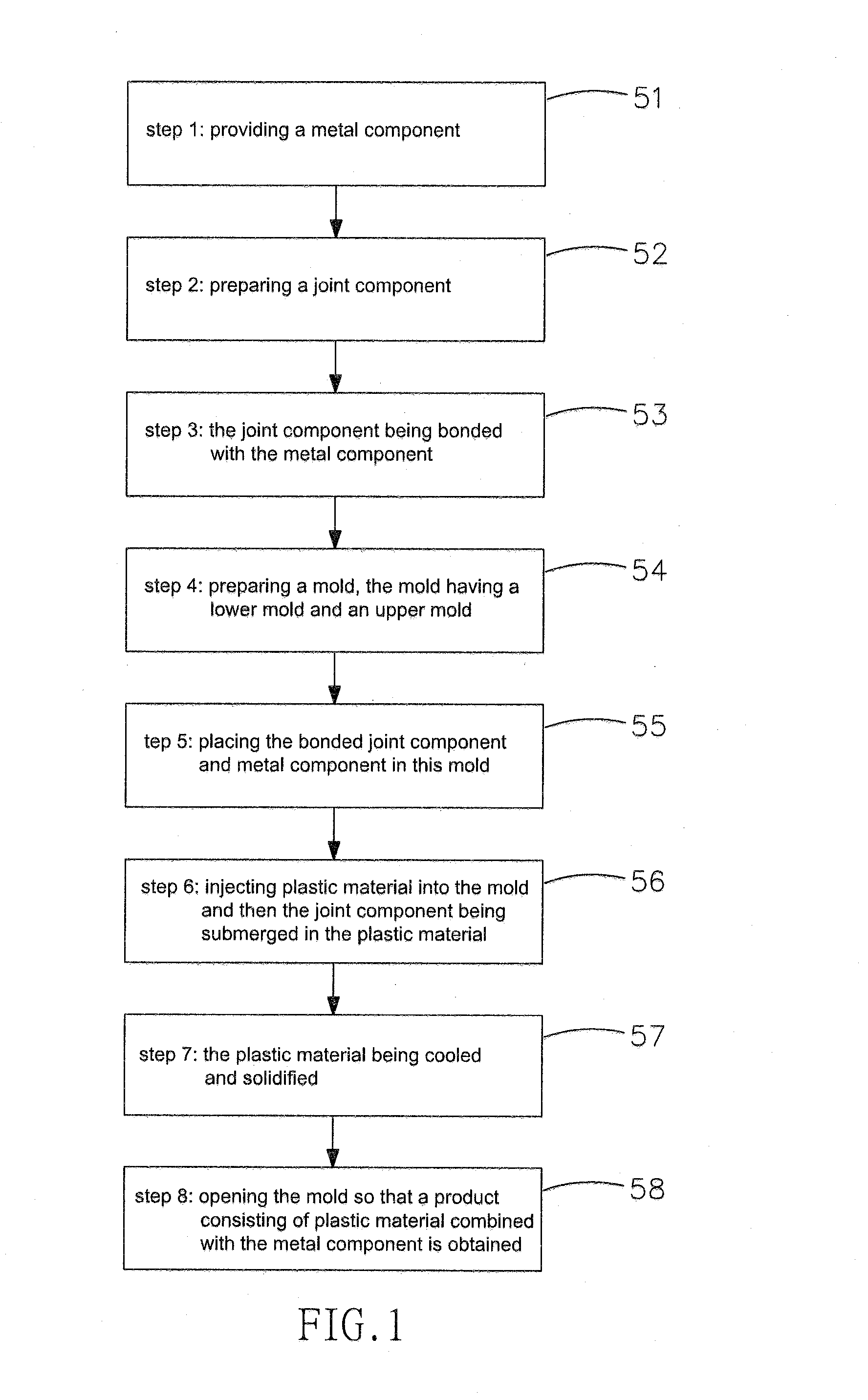
[0036]Referring to FIGS. 1 to 5, this invention is a method of selective plastic insert molding on metal component. It comprises the steps of:

[0037]step 1 (labeled 51): providing a metal component 10;

[0038]step 2 (labeled 52): preparing a joint component 20;

[0039]step 3 (labeled 53): the joint component 20 being bonded with the metal component 10;

[0040]step 4 (labeled 54): preparing a mold 30, the mold having a lower mold 31 and an upper mold 32;

[0041]step 5 (labeled 55): placing the bonded joint component 20 and metal component 10 in this mold 30;

[0042]step 6 (labeled 56): injecting plastic material 40 into the mold 30 and then the joint component 20 being submerged in the plastic material 40;

[0043]step 7 (labeled 57): the plastic material 40 being cooled and solidified; and

[0044]step 8 (labeled 58): opening the mold 30 so that a product consisting of plastic material 40 combined with the metal component 10 is obtained.

[0045]Based on the above-mentioned step 1 to step 8, the joint ...


PUM

PropertyMeasurementUnit
Structureaaaaaaaaaa
Adhesion strengthaaaaaaaaaa

Abstract

This invention discloses a method of selective plastic insert molding on metal component and its product. A metal joint component is bonded with a metal component. After which, the joint component is submerged in plastic so that the molded plastic can be secured on the metal component firmly. Hence, a desired plastic structure can be formed on the metal component. This invention can shorten the manufacturing process and reduce the cost. In addition, it solves the traditional bonding problem between the plastic and the metal component as well as the problem concerning processing time and high cost.

Description

CROSS-REFERENCE TO RELATED APPLICATION[0001]This application claims the benefit of the filing date of the U.S. Provisional Application No. 61 / 154,274, filed on Feb. 20, 2009, under 35 U.S.C. 119 (e) (1).BACKGROUND OF THE INVENTION[0002]1. Field of the Invention[0003]The present invention relates to a method of selective plastic insert molding on metal component. The metal joint component is bonded with a metal component. After which, the joint component is submerged in plastic so that the solidified plastic material can be secured on the metal component firmly. So, a structural member made by plastic material can be formed on the metal component.[0004]2. Description of the Prior Art[0005]If the housing of a mobile phone is made by metal, it will possess the metal's aesthetic appearance and unique touching feeling that is totally different to the ones of plastic. However, it is hard to bond plastic and metal together. If they are glued, the glued interface is not strong enough. So, t...

Claims


Application Information

Patent Timeline
IPC IPC(8): B32B7/08
CPCB29C45/14311B29C45/14778H04M1/026B29K2705/00B29L2031/3437B29C2045/14327Y10T428/249923
Inventor WANG, SHAUPOHYI, SHENG-HUNGSU, YI-CHUNG
Owner TAIWAN GREEN POINT ENTERPRISE
Learn More